
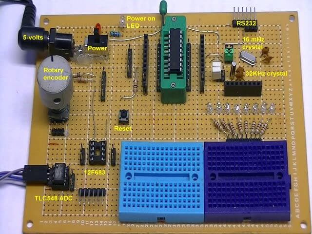
Fig. 1
Click here for larger image.
PIC16F628 Pulse Width Modulation Controls Brightness of LED
by Lewis Loflin
Follow @Lewis90068157
The following code snippet sets up the PWM hardware in the PIC16F628A. The output at RB3 is connected to an LED.
	BANKSEL 1 ; Bank 1
	MOVLW B'11111001'
	MOVWF PR2
	BANKSEL 0 ; Back Bank 0
	MOVLW B'00000101'
	MOVWF T2CON
	MOVLW 0 ; duty cycle
	MOVWF  CCPR1L ; duty cycle 0-255
	MOVLW B'00001100'
	MOVWF CCP1CON
Code example from 16F628A_PWM.asm contains PWM setup. The RB3 LED goes from off to bright in steps, then reverses back to off.
main

; Demo 2
; CCPR1L is 8-bit PWM duty cycle reg. 0-255.
; RB3 is PWM output to LED2 to GRD.
; LED2 on pin RB3 goes from off to bright in steps.
; Clear PWM register CCPR1L, LED2 = OFF
; Flip state of LED1 RB1 with XORWF
; W = 50, call delay Wx10ms = 500mSec.
; 2 loops = 1 Hz. rate on LED1 RB1
; Every loop 20 ADDed to CCPR1L duty cycle reg.
; LED2 gets brighter
; Every 1Hz 40 is ADDed to PWM CCPR1L
; Check STATUS bit C
; Exit loop if C = 1, C = 0 back aa
; Repeat until STATUS C bit = 1.
	clrf 	CCPR1L
aa	movlw 0x02
	xorwf PORTB, f
	movwf d'50'
	call Wx10ms ; LED ON 0.5 sec.
	movlw d'20'
	addwf CCPR1L, f
	btfss STATUS, C ; check carry
	goto aa

; CCPR1L is 8-bit PWM duty cycle reg. 0-255.
; RB3 is PWM output to LED2 to GRD.
; LED2 on pin RB3 goes from bright to off in steps.
; PWM register CCPR1L = 255, LED2 on RB3 is bright
; Flip state of LED1 RB1 with XORWF
; W = 50, call delay Wx10ms = 500mSec.
; 2 loops = 1 Hz. rate on LED1 on RB1
; Every loop 20 SUBed from PWM CCPR1L reg.
; LED2 get dimmer
; Every 1Hz 40 is SUBed from PWM CCPR1L
; Check STATUS bit C for borrow
; Exit loop if C = 0, C = 1 back  bb
; Repeat until STATUS C bit = 0.
	movlw d'255'
	movwf CCPR1L
bb	movlw 0x02
	xorwf PORTB, f
	movwf d'50'
	call Wx10ms ; LED ON 0.5 sec.
	movlw d'20'
	subwf CCPR1L, f
	btfsc STATUS, C ; check borrow
	goto bb

	goto	main
For how to calculate frequency and duty cycle for PIC PWM
see Working with Pulse-Width Modulation and the PIC Microcontroller
See How I got into Electronics

- You Tube Videos for this Series
- Home Built PIC Development Board
- PIC16F628 PIC Using Rotary Encoder to Operate Stepper Motor
- Using a Serial ADC with PIC16F628
- Calculating Pulse-Width Modulation with a PIC
- PIC16F84A-628A Hardware Time Delays
- PIC16F84A-628A Timer Interrupt Delays
- PIC16F84A-628A Pullups and Interrupts
- PIC16F84A-628A Hardware Interrupts Tutorial
- Projects using PIC16F628:
- Home Built PIC16F628 Prototyping Board
- Exploring the Microchip PIC in Assembly
- Using a Microchip PIC with TLC548 Serial ADC
- Controlling PIC Pulse Width Modulation with a Serial ADC
- Using TMR0 on a PIC with Interrupts
- External Clock Crystal with PIC16F628 TMR1 Generates Interrupt
- PIC Using Rotary Encoder to Operate Stepper Motor
- PIC16F628 Pulse Width Modulation Controls Brightness of LED
- Another way to Turn On-Off PWM in a PIC
- TLC548 Serial ADC Spec. Sheet
- Programming PIC16F84A-PIC16F628A Interrupts by Example
- PIC16F84A-PIC16F628A Pull Up Resistors with Interrupts
- Programming PIC16F84A-PIC16f628a Timers by Example
- Programming PIC16F84A-PIC16F628A TMR0 Interrupts
- Programming PIC16F84A Software Delay Routines by Example
Web site Copyright Lewis Loflin, All rights reserved.
If using this material on another site, please provide a link back to my site.