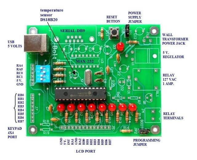
PIC Micorcontroller Pulse-Width Modulation Basics
For the background on this project see Introducing the BOLT PIC18F2550 Microcontroller Board.
As a newcomer to programming the Microchip PIC processors the lack of usable information on both the web and in the spec sheets proved challenging. Nowhere was this more so than with the pulse-width-modulation setup. My goal here is to produce working examples that make sense to those wanting to get into PIC programming, but are turned off by the lack of useful literature.
PICs have a strong point in following a certain pattern regardless of type and there are a lot of PICs out there. They add new features while retaining older hardware for the most part.
For my part I've worked with the 18F2550 in C and the 16F628 in assembly. Their PWM modules are the same. I wanted to learn to program these devices without reliance on user supplied files and find out directly how the hardware works underneath in order to interface various electronics components.
In addition learning to directly write the individual registers in C enables one to better understand assembly code which can be embedded into a C program. In cases such as the 16F628 with only 2k of user memory and 256 bytes of SRAM programming in C will overrun available resources in no time. So there it's all assembly language.
How to Work a Real World Example
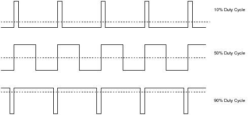
Note the above illustration. The period of a waveform is the reciprocal of the frequency. So the period of 5 kHz = 1 / 5000 = 0.0002. Duty cycle is the ratio of on time divided by period times 100. So with a period of 200 uSec and an on time 50 uSec we get 50/100 * 100 = 50%. With those values the on time for 10% is 20 uSec. and for 90% is 180 uSec.
In the example below I calculate the values to produce a 5 kHz 50 percent duty cycle square wave. The PWM module only uses TMR2 and I switch the output on/off at 1 second intervals by changing TRISBbits.TRISB3 from output to input.
#include <p18cxxx.h>
#include <delays.h>

void init_18F2550(void);
void delay_ms(int);

// See c018i.c in your C18 compiler dir
extern void _startup( void );
// For use of BOLT USB boot loader, otherwise set to 0x0000
#pragma code _RESET_INTERRUPT_VECTOR = 0x000800

void _reset( void )
{
  _asm goto _startup _endasm
}

#pragma code

void main()  {
  //user program
  init_18F2550();
  TRISB = 0 ;   // set PORTB as output
  PORTB = 0 ;  // assures TRISBbits.TRISB3 = 0

 /*
   * Using CCP2 module output on RB3
   * RB3 must set as an output
   * PWM Period = [(PR2) + 1] * 4 * TOSC *
   (TMR2 Prescale Value)
   * configure CCP module as 5000 Hz PWM output
   * PWM period = 1 / 5000 = 0.0002
   * crystal is 20 mHz but internal multipliers operates at 48 mHz.
   * Tosc = 1/ 48 mHz
   * TMR2 prescale  = 16
   * PR2 = 149
   * Reading on my frequency counter 5 kHz
 */

  // TMR2 period register for 5 kHz is 149 and prescale of 16.
  PR2 = 149;
  T2CON = 0b00000111 ;  // 0x07 TMR2 is on and prescale / 16
 /*
   bit 7 xx
   bits 6-3 postscale unused here
   bit 2 TMR2ON: Timer2 On bit
   1 = Timer2 is on
   0 = Timer2 is off
   bit 1-0 T2CKPS1:T2CKPS0:
   Timer2 Clock Prescale Select bits
   00 = Prescaler is 1
   01 = Prescaler is 4
   1x = Prescaler is 16
 */

  //The eight MSbs of the duty cycle are found in CCPR2L.
  CCPR2L = 0b00000000 ;  // 0x00 PWM off

 /*
   PWM duty cycle is 10-bit value of 0-1023
   The eight MSbs of the duty cycle are found in CCPR1L.
   CCP2CONbits.DC1B1 is bit 1
   CCP2CONbits.DC1B0 is bit 0
   bits 3-0 1100 = PWM mode: P1A,
   P1C active-high; P1B, P1D active-high
   See page 151 in spec sheet
   // only using 8 MSBs in this demo
 */
  CCP2CON = 0b00001100 ;  // 0x0C

 /*
   To calculate duty cycle:
   PWM duty cycle = (DCxB9:DCxB0 bits value) * Tosc *
   (TMR2 prescale value)
   Tosc = 1 / 48 mHz
   TMR2 prescaler = 16
   Frequency = 5 kHz; PWM period =  1 / 5000 = 0.0002
   For a duty cycle of 50 percent:
   0.0002 * .5 = value * 2.083 e-8 * 16
   value = 75 for a 50% duty cycle.
 */
  CCPR2L = 75; // set duty cycle
  // period reading on my frequency counter is 50%

  for(;;)   {
    TRISBbits.TRISB3 = 0; // turn on output
    delay_ms(1000); // on for 1 second
    // setting TRISBbits.TRISB3 = 1 turns off output
    TRISBbits.TRISB3 = 1; // turn off output
    delay_ms(1000); // off 1 second
  }
}  // end main()


//Ports initialized A, B, C
void init_18F2550(void)   {
  ADCON1=0x0F; // disables converters A/D
  CMCON=7;
  TRISB=0; //PORTB are outputs
  PORTB=0; // off LEDS
  TRISA=0X30;
  //RA4,RA5 are inputs. RA0,RA1,RA2,RA3 outputs
  TRISC=0X0F;
  //RC0,RC1 are inputs (MICROSWITCHES)
  INTCON2bits.RBPU=0;
  //pull-up resistors on port B (RB4...RB7).
}

void delay_ms(int i)   {
  long int j;
  for(j=0;j<i;j++)   {
    //48 MHZ, DELAY OF 1 MS APROX.
    Delay1KTCYx(12);
  }
}
See How I got into Electronics
Videos, Links, Downloads for the PIC18F2550 BOLT
- Introducing the BOLT PIC18F2550 Microcontroller Board
- PIC18F2550 BOLT with Serial LCD Display
- Using the MAX7219 with the 18F2550 Programs:
- MAX7219 Display Driver and a PIC Micro Controller
- MAX7219 Display Controller in the Non-Decode Mode with PIC
- Using TMR0 and Interrupts on the PIC18F2550
- YouTube Videos:
- My YouTube Channel
- MAX7219 display controller with 8X8 LED Matrix
- Programming the MAX7219 and 7-Segment Display
- Connecting PIC18F2550 to Parallel LCD Display
- Connecting PIC18F2550 to Serial LCD Displays
- Downloads:
- lewislcd.h My LCD H file
- Schematic Serial LCD
- BOLT_Template.zip
- Bolt Getting Started (pdf)

- Assembly language projects using PIC16F628:
- Exploring the Microchip PIC in Assembly
- Using a Microchip PIC with TLC548 Serial ADC
- Controlling PIC Pulse Width Modulation with a Serial ADC
- Using TMR0 on a PIC with Interrupts
- External Clock Crystal with PIC16F628 TMR1 Generates Interrupt
- PIC Using Rotary Encoder to Operate Stepper Motor
- PIC16F628 Pulse Width Modulation Controls Brightness of LED
- Another way to Turn On-Off PWM in a PIC
- TLC548 Serial ADC Spec. Sheet
Web site Copyright Lewis Loflin, All rights reserved.
If using this material on another site, please provide a link back to my site.