Programming PIC16F84A Software Delay Routines
by Lewis Loflin
Follow @Lewis90068157
See Programming PIC16F84A-PIC16F628A Interrupts Tutorial.
Software delay routines are useful and saves tying up hardware timers to be used for other purposes. The examples I've seen in Microchip PIC assembly are just confusing to modify and use. And often not accurate. Here I'll illustrate a more sane way to program software time days.
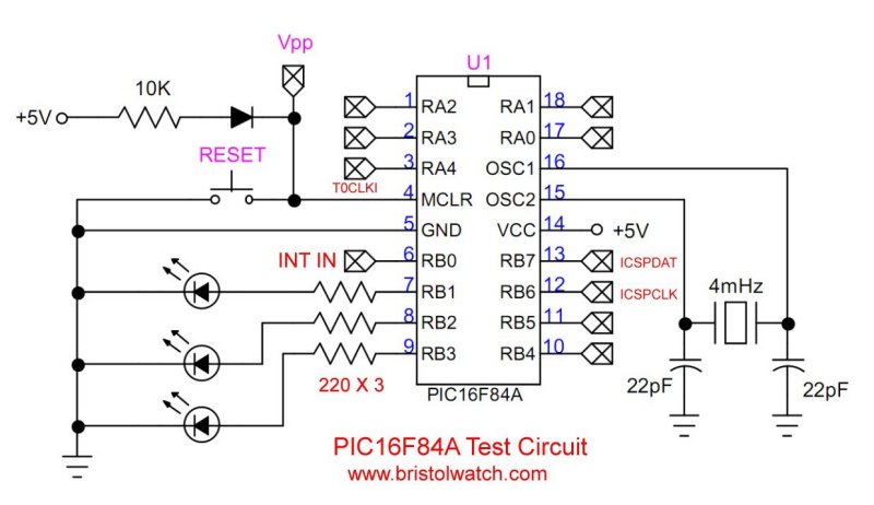
As shown in the video without delays the LED would appear to be on all the time.
First, one must know the frequency of the oscillator crystal, which is divided by 4. With a 4mHz oscillator produces a period of 1 uSec for most instructions except branching and jump instructions.
;=========================================
;	CLOCK: External 4MHz (instruction execution time: 1usec)
;	This is a basic start template for PIC16F84A
;	Includes delay routines
;	Program name: 16F84A_software_delay.asm
;	Date: 7-7-2024
;	Author: Lewis Loflin
;	MPLAB v8.92	compiler.
; 	Frequency = 1Hz.
;========================================
	list      p=16F84A
	#include <p16F84A.inc>
	errorlevel  -302

	; NOTE!!! Select proper chip for the compiler!

	__CONFIG  _CP_OFF & _PWRTE_ON & _WDT_OFF & _XT_OSC


;*****[ Data Storage Reg's ]*****
	CBLOCK  0x0C ; Assign each reg. from Bank 0 RAM area.
	CNT1
	CNT2
	CNT3
	CNT4
	B0
	B1
	B2
	temp1
	temp2
	ENDC ; Conclude Bank 0 RAM assignments.

	org	0 ;Setting Reset vector
	goto	setup ; RESET

	org 0x04  ; interrupt
	retfie                    ; return from interrupt

; main routine:
setup	; Program starts here !!!


	banksel 1
	; 1 = input, 0 = output
	movlw	b'11110001'	; portb, RB1-3 output, RB4-7, RA0 input
	movwf	TRISB		; set i/o configuration for portb
	banksel 0
		;jump back to bank 0 of pic.
	clrf PORTB		;clear all i/o's of portb

main

	movlw   0x02  ; xor (toggle) bit rb1 b'00000010'
	xorwf   PORTB, 1 ; 2 passes for each cycle
	movlw .50 ; delay 50 * 10msec. = 0.5 sec
	call wx10ms

goto main

; delay routines *************************************

; Calculating a 1mSec delay. 4mHz is divided by 4 internally to
; 1,000,000. Take reciprocal divide 1mSec by 1uSec = 1000.
; GOTO uses 2 cycles DECFSZ 1 cycle = 3 cycles or 3uSec.
; 3uSEC. * 82 * 4 = 1002uSec. or ~1mSec.

delay1ms
	movlw D'4'
	movwf CNT1
	movlw D'82'
	movwf CNT2
	decfsz CNT2, F
	goto $-1
	decfsz CNT1, F
	goto $-5
	return

delay10ms
	movlw .10
	goto $+2 ; skip next
wx1ms	; W * 1mSec.
	movwf CNT4
	call delay1ms
	decfsz CNT4, f
	goto $-2
	return


wx10ms	; W * 10mSec.
	movwf CNT3
	call delay10ms
	decfsz CNT3, f
	goto $-2
	return

end  ;End of source code.
- Operate PIC16F84A TMR0 from RA4/T0CKI Pulse Input
- Toggle ON-OFF LED Based on External Interrupt
- Programming PIC16F84A-PIC16f628a Timers by Example
- Programming PIC16F84A-PIC16F628A TMR0 Interrupts
- Programming PIC16F84A Software Delay Routines by Example
- YouTube videos:
- PIC16F84A-628A Hardware Time Delays
- PIC16F84A-628A Timer Interrupt Delays
- PIC16F84A-628A Pullups and Interrupts
- PIC16F84A-628A Hardware Interrupts Tutorial
- Microchip PIC related videos:
- How to Use K150 PIC Programmer
- Microchip PIC16F628A Basic H-Bridge Motor Control
- Microchip PIC16F628A Counts BCD on 8 LEDs
- PIC16F84A Operates H-Bridge Motor Control
- PIC16F84A Operates MOSFET H-Bridge
- Using Velleman K8048 PIC Development Board
- Arduino Port Registers Revisited
- Digispark ATtiny85 with MCP23016 GPIO Expander
- Safely Build Program a H-Bridge
- Build H-Bridge Motor Control Without Fireworks
- MOSFET H-Bridge for Arduino 2
- Microchip PIC16F84A H-Bridge Motor Control
- Microchip PIC16F628A Basic H-Bridge Motor Control
- PICAXE Operates H-Bridge Motor Controller
- PICAXE Microcontroller Controls Motor Speed - Direction
- PICAXE Projects
Web site Copyright Lewis Loflin, All rights reserved.
If using this material on another site, please provide a link back to my site.