Microchip PIC PIC18F2550 Using TMR0 Interrupts
In this demo we will use TMR0 to generate X number of interrupts and increment an integer variable called count. After a number of counts we will toggle a LED connected to Rb0.
The PIC18F2550 has three timers labeled TMR0 (8-bit or 16-bit), TMR1 (16-bit) and 8-bit TMR2.
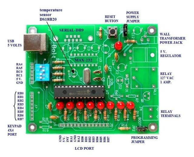
In this case I'm using the BOLT micro-controller board with a 20 mHz external crystal through internal multipliers is operating at 48 mHz.
The 48 mHz is divided by four then one merely selects a prescaler value (3 bits) from 2 to 256. In this case I selected divide by two giving me 6 mHz at TMR0.
The period of 6 mHz is 1.67 e-7. TMR0 operates in either 8-bit or 16-bit mode. Using 16-bit I can have a maximum value of 2^16 or 65536. Multiply 65536 * 1.67 e-7 = 0.011 ; 1/.011 = 91.5 Let's say 92 interrupts will equal 1 second.
This demo also shows how to setup MPLAB fir using interrupts.
Using the timers.h Library
The C18 compiler timers.h library can be useful for those not inclined to flipping individual register bits or tearing their hair out with frustrating and poorly written spec sheets. We have four functions to learn:
CloseTimerx Disable timer x.
OpenTimerx Configure and enable timer x.
ReadTimerx Read the value of timer x.
WriteTimerx Write a value into timer x.
Setting up the timer is the most critical step and one still has to setup interrupt bits. For example:
OpenTimer0( TIMER_INT_ON & T0_16BIT & T0_SOURCE_INT & T0_EDGE_RISE & T0_PS_1_2 )
This did the very same thing I did with T0CON = 0x80 and INTCONbits.TMR0IE = 1. I find this rather useless as an electronics person, but for those that are only programmers it could be a big help. See page 61 in MPLAB C18 Libraries.
What we did here was turn on TMR0 in 16-bit mode, enabled interrupts, use rising edge on the clock pulse, set the prescaler to divide by 2.
Using TMR0 in the 18F2550 Programming Example
See page 127 in spec sheet. 8 or 16 bits.
T0CON 0x0FD5, TMR0L 0x0FD6, TMR0H 0x0FD7

T0CON

bit 7 TMR0ON: Timer0 On/Off Control bit
1 = Enables Timer0
0 = Stops Timer0

bit 6 T08BIT: Timer0 8-bit/16-bit Control bit
1 = Timer0 is configured as an 8-bit timer/counter
0 = Timer0 is configured as a 16-bit timer/counter

bit 5 T0CS: Timer0 Clock Source Select bit
1 = Transition on T0CKI pin
0 = Internal instruction cycle clock (CLKO)

bit 4 T0SE: Timer0 Source Edge Select bit
1 = Increment on high-to-low transition on T0CKI pin
0 = Increment on low-to-high transition on T0CKI pin

bit 3 PSA: Timer0 Prescaler Assignment bit
1 = Timer0 prescaler is NOT assigned.
Timer0 clock input bypasses prescaler.
0 = Timer0 prescaler is assigned.
Timer0 clock input comes from prescaler output.

bit 2-0 T0PS2:T0PS0: Timer0 Prescaler Select bits
111 = 1:256 Prescale value
110 = 1:128 Prescale value
101 = 1:64 Prescale value
100 = 1:32 Prescale value
011 = 1:16 Prescale value
010 = 1:8 Prescale value
001 = 1:4 Prescale value
000 = 1:2 Prescale value
Setting up INTCON
Setting up interrupt with the INTCON register is very different in advanced processors such as the 18F2550 as opposed to 16F628A I've used with assembly. While both have interrupt capability, the 18F2550 has so many interrupt sources it has priority bits. They don't seem to change anything in this simple demo, but be cautious. I set RCONbits.IPEN to gain control of the other interrupts which I disabled for this. The following we must be concerned with:
INTCONbits.GIE must be set to enable interrupts;
INTCONbits.TMR0IE TMR0 Overflow Interrupt Enable bit must be set;
INTCONbits.TMR0IF TMR0 Overflow Interrupt Flag bit must be cleared by software before another interrupt can occur.
#include <p18cxxx.h>
#include <delays.h>

#define HIGH 1
#define LOW 0
#define Rb0  PORTBbits.RB0
#define delay_us	Delay10TCYx

// prototype declarations
void timer0_isr(void);
// interrupt service routine
void setup(void);
void init_18F2550(void);
void delay_ms(int);

// See c018i.c in your C18 compiler dir
extern void _startup( void );
#pragma code _RESET_INTERRUPT_VECTOR = 0x000800

void _reset( void )
{
  _asm goto _startup _endasm
}

#pragma code _HIGH_INTERRUPT_VECTOR = 0x000808

void _high_ISR (void)
{
  _asm goto timer0_isr _endasm
}

#pragma interrupt timer0_isr
#pragma code

unsigned int count = 0;    // Define variable cnt

void main()   {
  setup(); // setup PIC18F2550
  for (;;)   {
  } // idle here do nothing
} // end main

void setup()   {
  init_18F2550();
  PORTB = 0x00;
  // make sure IPEN is set
  RCONbits.IPEN = 1; //enable priority levels
  T0CON = 0x80; // TMR0 on, prescaler 1/2 16-bit mode
  // 48 MHZ / 4 = 12 MHZ Prescale / 2 = 6 MHZ
  // 1 / 6 MHZ = 1.67 e-7 * 2^16 = .011 Sec.
  INTCONbits.TMR0IE = HIGH; // enable TMR0 int
  // must be cleared after every interrupt
  INTCONbits.TMR0IF = LOW;  // Clear TMR0 IRQ flag
  INTCONbits.PEIE = HIGH;
  // PERIPHERAL INTERRUPT ENABLE REGISTER 1 bit
  INTCONbits.GIE = HIGH; 	//enable global interrupts
  TMR0L = 0;
  TMR0H = 0;
}

// interrupt service routine
// after 91 interrupts or 1 second toggle Rb0.
void timer0_isr() {
  count++;
  // Interrupt causes count to be incremented by 1
  if (count == 91)   {
    // 91 * .0109 Sec. = approx. 1 Sec
    Rb0 = !Rb0; // toggle Rb0
    count = 0;
  }
  INTCONbits.TMR0IF = 0;
  // clear TMR0 interrupt flag
}

//Ports initialized A, B, C
void init_18F2550(void)
{
  ADCON1=0x0F; 	// disables converters A/D
  CMCON=7;
  TRISB=0;	//PORTB are outputs
  PORTB=0;	// off LEDs
  TRISA=0X30;
  //Ra4,Ra5 are inputs (MICRO SWITCHES).
  // RA0,RA1,RA2,RA3 outputs
  TRISC=0X0F;
  //Rc0,Rc1 are inputs (MICRO SWITCHES)
  INTCON2bits.RBPU=0;
  //select pull-up resistors on port B (Rb4...Rb7).
}

//also available: delay_us(); delay in microseconds.
// 48MHZ / 4 = 12 MHZ; 1/12 MHZ = 8.33e-8
// 8.33e-8 * 12,000 = 1 mS.
// see delay.h in C18 compiler libraries
void delay_ms(int i)
{
  long int j;
  for(j=0;j<i;j++)
  {
    Delay1KTCYx(12);
    //48 MHZ, DELAY OF 1 MS APPROX.
  }
}
See How I got into Electronics
Videos, Links, Downloads for the PIC18F2550 BOLT
- Introducing the BOLT PIC18F2550 Microcontroller Board
- PIC18F2550 BOLT with Serial LCD Display
- Using the MAX7219 with the 18F2550 Programs:
- MAX7219 Display Driver and a PIC Micro Controller
- MAX7219 Display Controller in the Non-Decode Mode with PIC
- Using TMR0 and Interrupts on the PIC18F2550
- YouTube Videos:
- My YouTube Channel
- MAX7219 display controller with 8X8 LED Matrix
- Programming the MAX7219 and 7-Segment Display
- Connecting PIC18F2550 to Parallel LCD Display
- Connecting PIC18F2550 to Serial LCD Displays
- Downloads:
- lewislcd.h My LCD H file
- Schematic Serial LCD
- BOLT_Template.zip
- Bolt Getting Started (pdf)

- Assembly language projects using PIC16F628:
- Exploring the Microchip PIC in Assembly
- Using a Microchip PIC with TLC548 Serial ADC
- Controlling PIC Pulse Width Modulation with a Serial ADC
- Using TMR0 on a PIC with Interrupts
- External Clock Crystal with PIC16F628 TMR1 Generates Interrupt
- PIC Using Rotary Encoder to Operate Stepper Motor
- PIC16F628 Pulse Width Modulation Controls Brightness of LED
- Another way to Turn On-Off PWM in a PIC
- TLC548 Serial ADC Spec. Sheet
Web site Copyright Lewis Loflin, All rights reserved.
If using this material on another site, please provide a link back to my site.