PIC18F2550 BOLT Interfacing SN74164 SSR LCD Display
by Lewis Loflin
YouTube video: Connecting PIC18F2550 to Serial LCD Displays
For background information see:
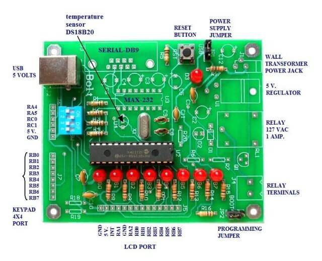
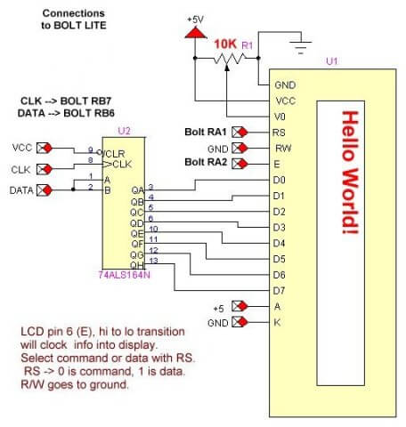
/*
We recommend using this with MPLAB v.8.63 and C18 compiler v.3.40.
 File (.hex) resulting from the compilation must be loaded into Bolt card with PC
 software "Bolt 1.0.1".

 The BOLT has a 2k boot loader for use of USB
 to program.

 It is important to integrate in the C project, file
 "rm18f2550.lkr", which is a linker script for C18.

 See http://www.puntoflotante.net/BOLT-V-LITE-SYSTEM.htm

 This is written to operate a HD44780 LCD display connected
 to a 74164 serial shift register. The connections to the BOLT
 are as follows:

 LCD pin 6 (E or RA2), HIGH to LOW transition will clock
 info into display. Select command or data with RS (RA1).
 RS -> 0 is command, 1 is data. R/W goes to ground.

 RB6 is DATA and RB7 is CLK

 The demo below demonstrates how to place strings, floats, int,
 binary, and char on the LCD display.

 This exact code will work on a parallel LCD connection
 by changing ssrWrite() as illustrated at end of page.

 Memory usage 1791 of 16382
 and SRAM 512 of 2048

 */

//EXTERNAL CRYSTAL=20 MHZ
//EFFECTIVE FREQUENCY=48 MHZ DUE TO PLL MULTIPLIERS
#include <p18cxxx.h>
#include <delays.h>
// #include <stdio.h>	//library sprintf() doesn't work
#include <stdlib.h>		//library atoi(), atof()
// #include "18F2550BOLT.h" // not needed here
// adc.h needed if using BOLT-ADC.h
// must be above #include "BOLT-ADC.h"
// #include <adc.h>


#define HIGH 1
#define LOW 0
#define Line1 0x80
#define Line2 0xC0


#define RA4  PORTAbits.RA4
#define RA5  PORTAbits.RA5
#define RC0  PORTCbits.RC0
#define RC1  PORTCbits.RC1
#define RA1  PORTAbits.RA1
#define RA2  PORTAbits.RA2
#define RA3  PORTAbits.RA3
#define RB0  PORTBbits.RB0
#define RB1  PORTBbits.RB1
#define RB2  PORTBbits.RB2
#define RB3  PORTBbits.RB3
#define RB4  PORTBbits.RB4
#define RB5  PORTBbits.RB5
#define RB6  PORTBbits.RB6
#define RB7  PORTBbits.RB7
#define delay_us	Delay10TCYx

// FUNCTION DECLARATIONS
// these work with my serial SN74164 LCD
void ssrWrite(char);
void LcdInit(void);
void typeChar(char);
void writeCommand(char);
void typeln(const char* s);
void ClrLcd(void);
void typeInt(int);
void gotoLcd(int);
void typeFloat(float);
void typeBinary(unsigned char);

void open_adc(void);
int read_adc(void);
void init_bolt(void);
void delay_ms(int);

// See c018i.c in your C18 compiler dir
extern void _startup( void );

// this is for 2k boot loader
#pragma code _RESET_INTERRUPT_VECTOR = 0x000800

// this is required
void _reset( void )
{
  _asm goto _startup _endasm
}

// this is required
#pragma code

int j;
float tfloat;
// we can declare strings outside main()
// note that 4spaces[] is illegal!
// but char c66[] = "c66"; is legal
// string data uses up SRAM - 4 spaces is 4 bytes
const char fourSpaces[] = "    ";
const char myString[] = "It works!";


void main()
{
  //user program

  init_bolt();
  open_adc();
  LcdInit();


  gotoLcd(Line1);
  typeln(myString); // type char string
  gotoLcd(Line1 + sizeof(myString));
  typeInt(56); // type an int
  gotoLcd(Line2);
  tfloat = -3.0016;
  // display neg float with zeros!
  typeFloat(tfloat);
  gotoLcd(Line2 + 9);
  typeChar(' '); // type a space
  typeChar('J');
  typeChar('=');
  // LCD 2 line X 16 char
  // got to a specific location line 2
  // will display potentiomer value
  for (;;)   {  // loop forever
    gotoLcd(Line2 + 12);
    typeln(fourSpaces); // type a char string
    gotoLcd(Line2 + 12);
    j = read_adc();
    typeInt(j);
    delay_ms(500);
  }


}


void typeChar(char val)   {
  RA1 = HIGH; // char mode
  ssrWrite(val);
  RA2 = LOW;
  delay_ms(5);
  RA2 = HIGH; // E
}

void writeCommand(char val)   {
  RA1 = LOW; // make sure RS is LOW
  ssrWrite(val); // send byte to 74164
  RA2 = LOW;
  delay_ms(10);
  RA2 = HIGH; // E
}


/*
LCD pin 6 (E or RA2), HIGH to LOW transition will clock
 info into display. Select command or data with RS (RA1).
 RS -> 0 is command, 1 is data. R/W goes to ground.
 */

void LcdInit(void) {
  //	  RB6 DATA setup LCD pins
  //    RB7 = LOW; // CLK
  //   RA1 = LOW; // RS in command mode default

  RA1 = LOW; // make sure RS is LOW
  RA2 = LOW;
  delay_ms(1);
  ssrWrite(0x38);
  delay_ms(5);
  RA2 = HIGH; // 2 lines X 16 char 8 bits mode
  RA2 = LOW;
  delay_ms(1);
  ssrWrite(0x0F);
  delay_ms(5);
  RA2 = HIGH;  // blinking cursor
  RA2 = LOW;
  delay_ms(1);
  ssrWrite(0x01);
  delay_ms(5);
  RA2 = HIGH;  // clear display fills
  RA2 = LOW;
  delay_ms(1);
  ssrWrite(0x02);
  delay_ms(5);
  RA2 = HIGH;  // Home
}


void typeln(const char *s)   {

  while( *s ) typeChar(*(s++));

}

void ClrLcd(void)   {
  ssrWrite(0x01);
  RA2 = LOW;
  delay_ms(5);
  RA2 = HIGH;  // clear display fills
  ssrWrite(0x02);
  RA2 = LOW;
  delay_ms(5);
  RA2 = HIGH;  // Home
}


// doesn't work for HEX or OCT
void typeInt(int k)   {
  char array1[10];
  itoa(k, array1);  // use above
  typeln(array1);
}

// go to location on LCD
void gotoLcd(int temp)   {
  writeCommand(temp);
}


// use type casting
void typeFloat(float myFloat)   {
  int temp = myFloat; // convert to int
  typeInt(temp);
  typeChar('.');
  if (myFloat < 0)   {
    myFloat = myFloat * -1;
    temp = temp * -1;
  }
  myFloat = (myFloat - temp) * 10000;
  temp = myFloat;  // convert to int
  if (temp < 1000) typeChar('0');
  if (temp < 100) typeChar('0');
  if (temp < 10) typeChar('0');
  typeInt(temp);
}


// The analog input channels must have their
// corresponding TRIS bits selected as an input.
void open_adc(void)   {
  //INITIALIZE CHANNEL 4
  /*	OpenADC( ADC_FOSC_64 &
   	ADC_RIGHT_JUST &
   	ADC_12_TAD,
   	ADC_CH4 &
   	ADC_INT_OFF, 15);
   */
  // does the same as above without adc.h
  ADCON0 = 0x11;  // set for CH4, Bit 0 ADON = 1
  ADCON1 = 0x3F;  // all digital just for setup
  ADCON2 = 0xAE;	// see page 257 spec sheet
  // disable interrupt
  PIR1bits.ADIF = HIGH;
  PIE1bits.ADIE = LOW;
}

int read_adc(void)   { //RETURNS WITH RESULT OF ADC
  /*	int val;
   	ADCON1=10; //ACTIVATE CHANNEL 4
   	ConvertADC();  // initiate conversion
   	while( BusyADC() );
   // wait for end of conversion
   	val = ReadADC();  // reads result
   	ADCON1=15;  // CHANNEL 4 off
   	return val;
   */

  // does the same thing as above without adc.h
  // on BOLT ADCON1bits.VCFG0 = 1;
  // VREF+ (AN3) and not VCC
  int val;
  ADCON1=10;
  // ADCON1bits.ADON = 0 turn off for read
  ADCON0bits.GO = 1;
  // initiate conversion
  while( ADCON0bits.GO );
  // wait for LOW - end of conversion
  val = (ADRESH * 256) + ADRESL;
  // reads/calculates result
  ADCON1=15;	//CHANNEL 4 off
  return val;
}

// output byte in binary
void typeBinary(unsigned char c)   {
  int i;
  char bit;
  for (i = 0; i < 8; i++)   {
    bit = c & 0b10000000;
    if (bit) typeChar('1');
    else typeChar('0');
    c = c << 1;
  }

}

//Ports initialized A, B, C
void init_bolt(void)   {
  ADCON1=0x0F; // disables converters A/D
  CMCON=7;
  TRISB=0; //PORTB are outputs
  PORTB=0; // off LEDS
  TRISA=0X30;
  //RA4,RA5 are inputs. RA0,RA1,RA2,RA3 outputs
  TRISC=0X0F;
  //RC0,RC1 are inputs (MICROSWITCHES)
  INTCON2bits.RBPU=0;
  //pull-up resistors on port B (RB4...RB7).
}


void delay_ms(int i)   {
  long int j;
  for(j=0;j<i;j++)   {
    //48 MHZ, DELAY OF 1 MS APROX.
    Delay1KTCYx(12);
  }
}

// shift data to 74164
void ssrWrite(char val)  {
  int j;
  for(j=1; j<=8; j++)  {   // shift out MSB first
    unsigned char  temp = val & 0x80; // MSB out first
    if (temp == 0x80) RB6 = HIGH; // RB6 DATA
    else RB6 = LOW;
    RB7 = HIGH;
    delay_us(20);
    RB7 = LOW;
    val = val << 1; // shift one place left
  }  // next j
}

/*

 // use for parallel LCD connection
 void ssrWrite(char val)  {
 	PORTB = val;
 }

 */
See How I got into Electronics
Videos, Links, Downloads for the PIC18F2550 BOLT
- Introducing the BOLT PIC18F2550 Microcontroller Board
- PIC18F2550 BOLT with Serial LCD Display
- Using the MAX7219 with the 18F2550 Programs:
- MAX7219 Display Driver and a PIC Micro Controller
- MAX7219 Display Controller in the Non-Decode Mode with PIC
- Using TMR0 and Interrupts on the PIC18F2550
- YouTube Videos:
- My YouTube Channel
- MAX7219 display controller with 8X8 LED Matrix
- Programming the MAX7219 and 7-Segment Display
- Connecting PIC18F2550 to Parallel LCD Display
- Connecting PIC18F2550 to Serial LCD Displays
- Downloads:
- lewislcd.h My LCD H file
- Schematic Serial LCD
- BOLT_Template.zip
- Bolt Getting Started (pdf)

- Assembly language projects using PIC16F628:
- Exploring the Microchip PIC in Assembly
- Using a Microchip PIC with TLC548 Serial ADC
- Controlling PIC Pulse Width Modulation with a Serial ADC
- Using TMR0 on a PIC with Interrupts
- External Clock Crystal with PIC16F628 TMR1 Generates Interrupt
- PIC Using Rotary Encoder to Operate Stepper Motor
- PIC16F628 Pulse Width Modulation Controls Brightness of LED
- Another way to Turn On-Off PWM in a PIC
- TLC548 Serial ADC Spec. Sheet
Web site Copyright Lewis Loflin, All rights reserved.
If using this material on another site, please provide a link back to my site.