PIC18F2550 Interfacing-Programming MAX7219 Display Controller
YouTube video: Programming the MAX7219 and 7-Segment Display
The following demonstrates the use of the MAX7219 display driver with a PIC18F2550 Microcontroller.
We demonstrate how to convert an integer to binary coded decimal along serial shift routines and how to program the MAX7219.
The MAX7219 is a serial input/output common-cathode display driver that interfaces microprocessors to a 7-segment numeric LED displays of up to 8 digits, bar-graph displays, or 64 individual LEDs.
Included on-chip are a BCD code-B decoder, multiplex scan circuitry, segment and digit drivers, and an 8x8 static RAM that stores each digit. Only one external resistor is required to set the segment current for all LEDs.
A convenient 4-wire serial interface connects to all common uPs. Individual digits may be addressed and updated without rewriting the entire display. The MAX7219 will also allow the user to select code- B decoding or no-decode for each digit.
The devices include a 150uA low-power shutdown mode, analog and digital brightness control, a scanlimit register that allows the user to display from 1 to 8 digits, and a test mode that forces all LEDs on.
- Related added Nov. 15, 2013:
- Arduino with Serially Interfaced MAX7219 Operates 8X8 LED Matrix
- Arduino RTC Clock with MAX7219 8-Digit LED Display
- BCD Conversion with Arduino Displayed on MAX7219
#include <p18cxxx.h>
#include <delays.h>

#define HIGH 1
#define LOW 0
#define CS        PORTBbits.RB5
#define DATA_bit  PORTBbits.RB6
#define SERCLK    PORTBbits.RB7
#define delay_us	Delay10TCYx

// function declarations
void ssrOut(unsigned char);
void pulseCS(void);
void init_MAX7219(void);
void writeMAX7219(char, char);

void delay_ms(int);
void init_18F2250(void);

// See c018i.c in your C18 compiler dir
extern void _startup( void );

#pragma code _RESET_INTERRUPT_VECTOR = 0x000800
void _reset( void )
{
    _asm goto _startup _endasm
}

#pragma code

int i, j, digit, count;

void main()
{
	init_18F2550();
    init_MAX7219();
	count = 9999;
	// convert to BCD send to MAXMAX7219
	for (i=0; i<=count; i++)   {
	j = i;
	// get 1st digit of j
	digit = j % 10; // MOD J
	writeMAX7219(1, digit);
	// get 2nd digit of j
	j = j / 10;
	digit = j % 10; // MOD j
	writeMAX7219(2, digit);
	// get 3rd digit of j
	j = j / 10;
	digit = j % 10; // MOD j
	writeMAX7219(3, digit);
	// get 4th digit of j
	j = j / 10;
	digit = j % 10; // MOD j
	writeMAX7219(4, digit);
	delay_ms(200);
	} // end for
} //end main


// shift data to MAX7219
// Rb7 -> SERCLK, Rb6 -> DATA_bit, Rb5 -> CS not
void ssrOut(unsigned char val)  {
	int j;
    for(j=1; j<=8; j++)  {   // shift out MSB first
    unsigned char  temp = val & 0x80; // MSB out first
    if (temp == 0x80) DATA_bit = HIGH; // Rb6 DATA
    else DATA_bit = LOW;
	SERCLK = HIGH;
	delay_us(20);
	SERCLK = LOW;
    val = val << 1; // shift one place left
  }  // next j
}

void writeMAX7219(char address, char data)   {
	if ((address < 1) || (address > 8)) return;
	ssrOut(address); // valid numbers 1-8
	ssrOut(data);
	pulseCS();
}


void pulseCS(void)   {
	CS = HIGH;
	delay_ms(1);
	CS = LOW;
}


void init_MAX7219(void)   {
	CS = LOW; // CS NOT

	// set decode mode
	ssrOut(0x09); // address
	// ssrOut(0x00); // no decode
	ssrOut(0xFF); // 4-bit BCD decode eight digits
	pulseCS();

	// set intensity
	ssrOut(0x0A); // address
	ssrOut(0x0D); // 5/32s
	pulseCS();

	// set scan limit 0-7
	ssrOut(0x0B); // address
	// ssrOut(0x07); // 8 digits
	ssrOut(0x03); // 4 digits
	pulseCS();

	// clear MAX7219 all zeros
	// BCD mode all off otherwise
	for(i=1; i<=8; i++)   {
		ssrOut(i);
		ssrOut(0x00);
		pulseCS();
   }

	// set for normal operation
	ssrOut(0x0C); // address
	// ssrOut(0x00); // Off
	ssrOut(0x01);  // On
	pulseCS();

}


void delay_ms(int i)
{
	long int j;
	for(j=0;j<i;j++)
	{
	Delay1KTCYx(12); 	//48 MHZ, DELAY OF 1 MS APPROX.
	}
}

//Ports initialized etc.
void init_18F2250(void)   {
	// disables converters A/D
	ADCON1=0x0F;
	// comparators off
	CMCON=7;
	//PORTB are outputs
	TRISB=0;
	// off LEDs
	PORTB=0;
	//Ra4,Ra5 are inputs Ra0,Ra1,Ra2,Ra3 outputs
	TRISA=0X30;
	//Rc0,Rc1 are inputs (MICRO SWITCHES)
	TRISC=0X0F;
	//select pull-up resistors on port B (Rb4...Rb7).
	INTCON2bits.RBPU=0;
}
See How I got into Electronics
Videos, Links, Downloads for the PIC18F2550 BOLT
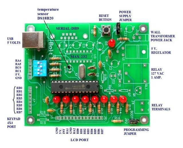
- Introducing the BOLT PIC18F2550 Microcontroller Board
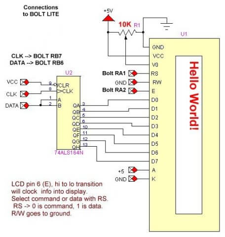
- PIC18F2550 BOLT with Serial LCD Display
- Using the MAX7219 with the 18F2550 Programs:
- MAX7219 Display Driver and a PIC Micro Controller
- MAX7219 Display Controller in the Non-Decode Mode with PIC
- Using TMR0 and Interrupts on the PIC18F2550
- YouTube Videos:
- My YouTube Channel
- MAX7219 display controller with 8X8 LED Matrix
- Programming the MAX7219 and 7-Segment Display
- Connecting PIC18F2550 to Parallel LCD Display
- Connecting PIC18F2550 to Serial LCD Displays
- Downloads:
- lewislcd.h My LCD H file
- Schematic Serial LCD
- BOLT_Template.zip
- Bolt Getting Started (pdf)

- Assembly language projects using PIC16F628:
- Exploring the Microchip PIC in Assembly
- Using a Microchip PIC with TLC548 Serial ADC
- Controlling PIC Pulse Width Modulation with a Serial ADC
- Using TMR0 on a PIC with Interrupts
- External Clock Crystal with PIC16F628 TMR1 Generates Interrupt
- PIC Using Rotary Encoder to Operate Stepper Motor
- PIC16F628 Pulse Width Modulation Controls Brightness of LED
- Another way to Turn On-Off PWM in a PIC
- TLC548 Serial ADC Spec. Sheet
Web site Copyright Lewis Loflin, All rights reserved.
If using this material on another site, please provide a link back to my site.