Fig. 1 Click for larger image.
Use TC4420 MOSFET Driver for Simple H-Bridge Circuit
by Lewis Loflin
Click on images for larger image.
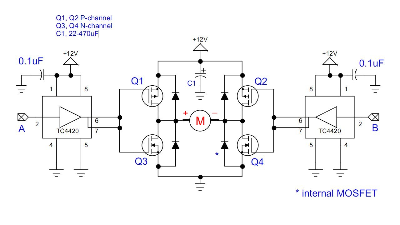
Here I will illustrate how to build an H-bridge motor control using 4 MOSFETs and 2 TC4420 MOSFET drivers, plus a few capacitors.
According to the manufacturer:
The TC4420/TC4429 are 6A (peak), single-output MOSFET drivers. The TC4429 is an inverting driver while the TC4420 is a non-inverting driver. These drivers are fabricated in CMOS for lower power and more efficient operation versus bipolar drivers.
Both devices have TTL/CMOS compatible inputs that can be driven as high as VDD + 0.3V or as low as –5V without upset or damage to the device. This eliminates the need for external level-shifting circuitry.
The output swing is rail-to-rail, ensuring better drive voltage margin, especially during power-up/power-down sequencing. Propagational delay time is only 55ns (typical) and the output rise and fall times are only 25ns (typical) into 2500pF across the usable power supply range.
I have used these and they work very well. The circuit is shown in Fig. 1. It has two inputs A and B. Yes one can connect and inverter between A and B for a single input, but to turn the motor off means disconnecting the power. Also tow of the modes will be unavailable.
In most cases the diodes are internal to the MOSFETs. Use MOSFETs with low Rds(on) values such as the IRFZ44N (N-channel) and IRF4905 (p-channel).
the maximum motor voltage is 18 volts.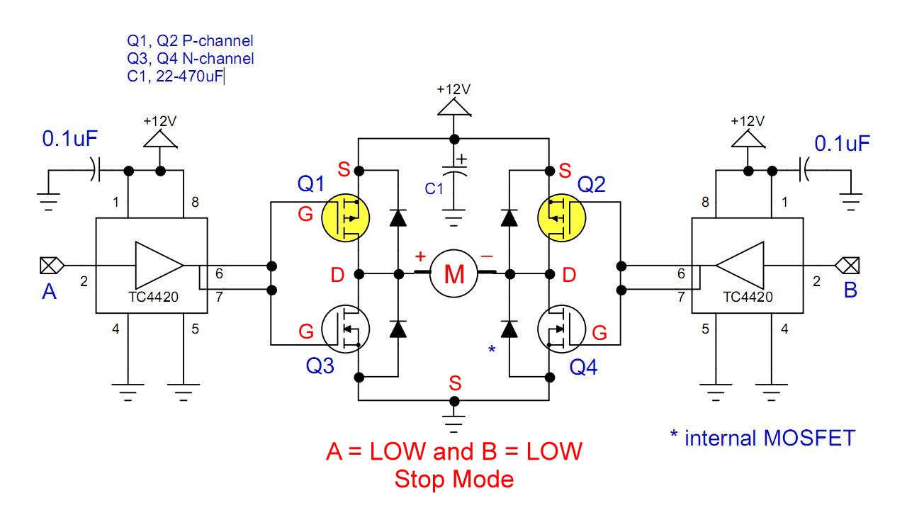
Fig. 2 Click for larger image.
Fig. 2 illustrates the STOP mode with both p-channels turned on. Both A and B are LOW.
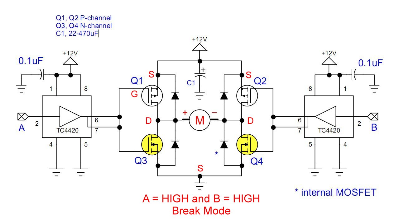
Fig. 3 Click for larger image.
Fig. 3 illustrates the BREAK mode with both N-channels on. Both A and B are HIGH.
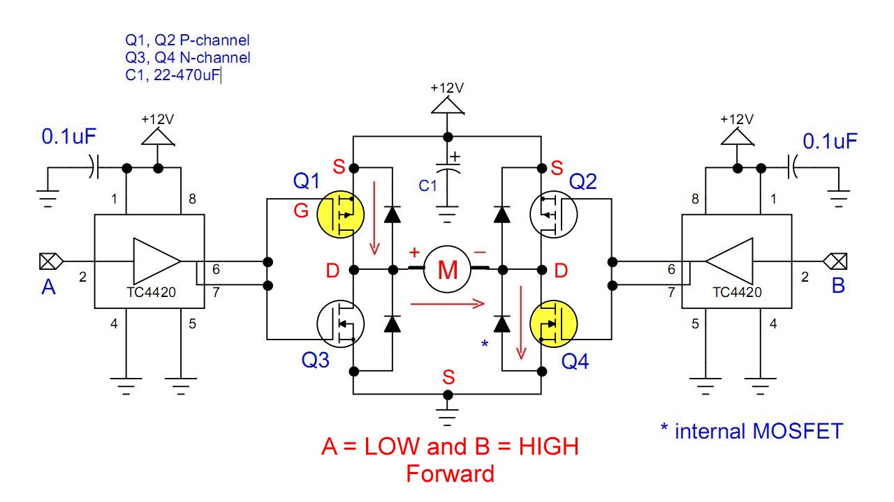
Fig. 4 Click for larger image.
Fig. 4 illustrates the FORWARD mode. A is LOW turning on Q1 while B is HIGH turning on Q4 to complete the current path.
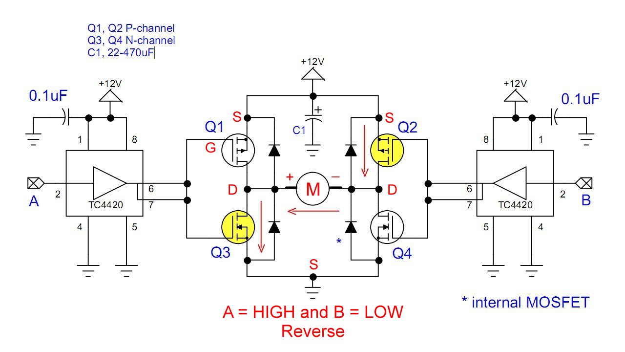
Fig. 5 Click for larger image.
Fig. 5 illustrates the REVERSE mode. A is HIGH turning on Q3 while B is LOW turning on Q2.
![]()
- Introduction TC4420-TC4429 MOSFET Drivers
- Use TC4420 MOSFET Driver for Simple H-Bridge Circuit
- TC4420 MOSFET Driver Various Circuits
- TC4420 MOSFET Driver Replacement Circuits
- YouTube Videos
- Introduction TC4420-TC4429 MOSFET Drivers
- Circuit Examples for TC4420-TC4429 MOSFET Drivers
- TC4420 H-Bridge Circuit
- Quick navigation of this website:
- Basic Electronics Learning and Projects
- Basic Solid State Component Projects
- Arduino Microcontroller Projects
- Raspberry Pi Electronics, Programming
- TC4420 MOSFET Driver Replacement Circuits
- TB6600 Stepper Motor Driver with Arduino
- Interfacing Microcontrollers to CMOS and MOSFET Circuits
- Simplified CMOS-MOSFET H-Bridge Circuit
- Tri-State H-Bridge using CD4093B CMOS Circuit
- Common Collector Opto-Isolated Bipolar Transistor Switches
- Compare 2N3055 MJE10005 Transistor Power Switches
- Compare 2N3055 MJE10005 Transistor Power Switches
- Optical Isolation of H-Bridge Motor Controls
- All NPN Transistor H-Bridge Motor Control
- Transistor Driver Circuits
- ULN2003A Darlington Transistor Array with Circuit Examples
- Tutorial Using TIP120 and TIP125 Power Darlington Transistors
- Driving 2N3055-MJ2955 Power Transistors
- Understanding Bipolar Transistor Switches
- N-Channel Power MOSFET Switching Tutorial
- P-Channel Power MOSFET Switch Tutorial
- Build a Transistor H-Bridge Motor Control
- H-Bridge Motor Control with Power MOSFETs
- More Power MOSFET H-Bridge Circuit Examples
- Build a High Power Transistor H-Bridge Motor Control
- H-Bridge Motor Control with Power MOSFETs Updated
- Opto-Isolated Transistor Drivers for Micro-Controllers
Web site Copyright Lewis Loflin, All rights reserved.
If using this material on another site, please provide a link back to my site.