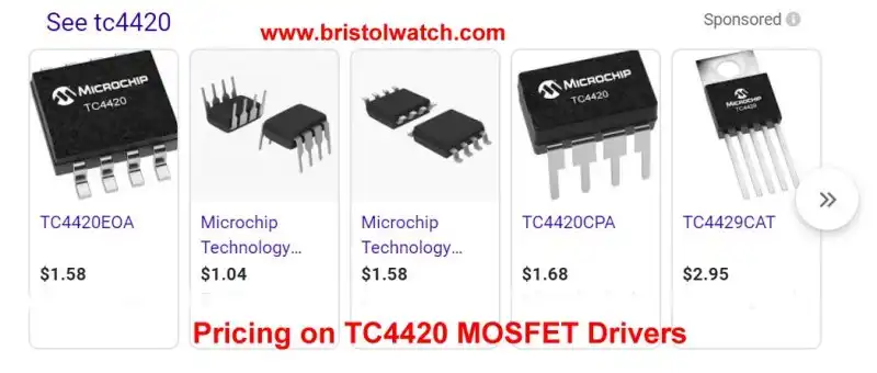
Fig. 1 TC4420 MOSFET driver case styles and prices.
TC4420 MOSFET Driver Replacement Circuits
by Lewis Loflin
The TC4420-29 are used as MOSFET drivers. They do a good job but are limited to 18-volts and perhaps not easy to find.
Here I will present alternative circuits. The purpose is to learn various circuit combinations.
The various circuit combinations are presented below. I have built and tested all of these combinations.
Before you start to freak out note the following: the spike suppressor diodes are INTERNAL to the MOSFETs used here and assumed to be. I don't draw them into the schematics to keep down clutter.
For current flow I use conventional flow even though I know it is wrong. That is what is taught in college and what most people are used to.
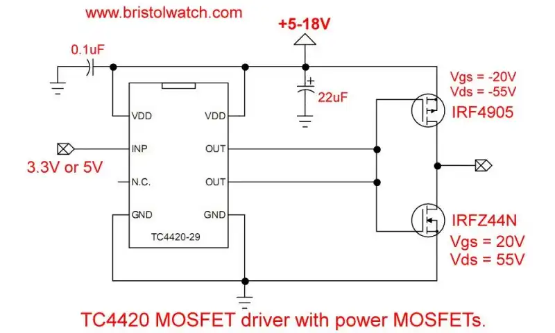
Fig. 2 TC4420 MOSFET driver with MOSFETs
Fig. 2 is the typical connections for a TC4420 (non-inverting) toTC4429 (inverting) MOSFET drivers. The design allows use of either 5-volt or 3.3-volt microcontrollers. No other level shifting circuitry needed.
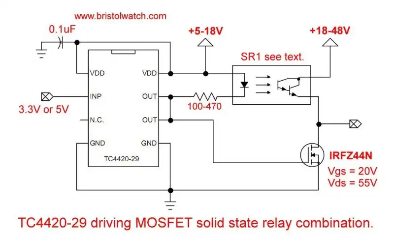
Fig. 3 TC4420 MOSFET driver with MOSFET and bipolar transistor optocoupler switch.
Fig. 3 uses an opto-coupler bipolar transistor combination to get past the 18-volt limit on a TC4420 and the 20-volt Vgs on a p-channel MOSFET.
This was part of an earlier project.
For SR1 see Common Collector Opto-Isolated Bipolar Transistor Switches.
The rest of this page is how to build your own circuits without having to buy a TC4420 or TC4429.
I can use a higher motor drive voltage than a direct connection to a TC4420 will allow.
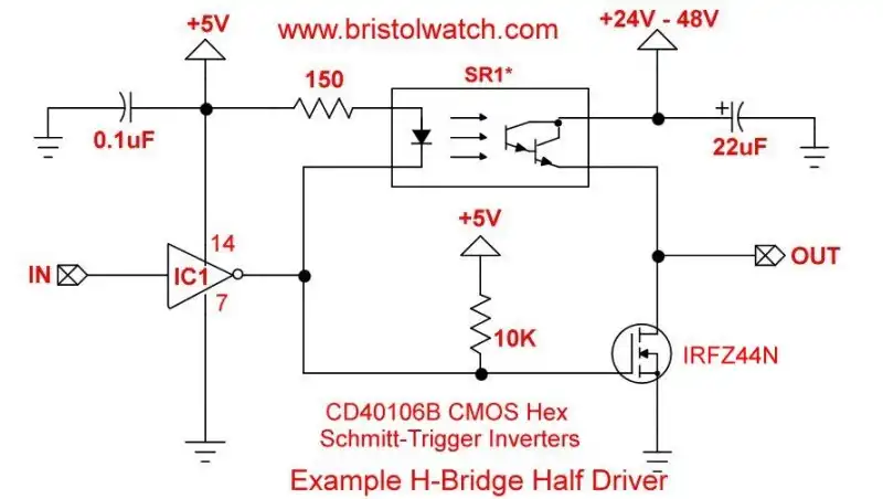
Fig. 4 Half H-bridge with CD40106 Schmitt-Trigger input.
In Fig. 4 I replaced the TC4420 with one Schmitt inverter from a CD40106. It contains 6 Schmitt trigger inverters.
The voltage on the CD40106 pin 14 must match the microcontroller logic level. If the logic is 3.3V then pin 14 must be 3.3V.
CMOS logic operates from 3-15 volts.
The use of SR1 allows one to separate the logic voltage from the higher motor voltage.
This circuit is non-inverting - high in is high, out etc.
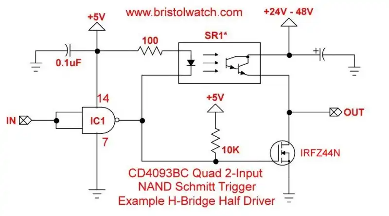
Fig. 5 Half H-bridge with CD4093 Schmitt-Trigger input.
The circuit in Fig. 5 operates identical to Fig. 4 except we use a CD4092 quad, 2-input NAND gate. This also has a Schmitt trigger input. There are four complete NAND gates in a 14-pin DIP.
This circuit is also non-inverting.
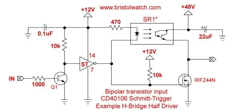
Fig. 6 Half H-bridge with bipolar transistor with CD40106 Schmitt-Trigger.
In Fig. 6 I used a NPN bipolar transistor on the input. This allows one to separate the CMOS CD40106, etc. voltage from the microcontroller voltage.
Q1 can be a 2N2222, etc.
Again I used SR1 to allow the higher motor voltage than the CMOS voltage.
If the motor voltage is under 15-volts then the CMOS and motor voltage can use the same source voltage. Replace SR1 with p-channel MOSFET.
This circuit is inverting - high in is low out, etc.
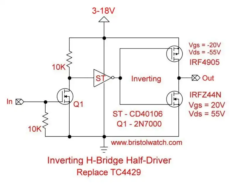
Fig. 7 Half H-bridge with MOSFET transistor input with CD40106 Schmitt-Trigger.
In Fig. 7 I replaced Q1 bipolar transistor with a 2N7000 MOSFET. Operation is the same. This circuit is also inverting.
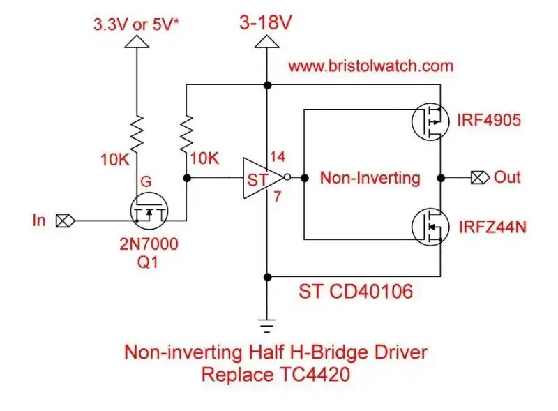
Fig. 8 Non-Inverting Half H-bridge with MOSFET transistor input with CD40106 Schmitt-Trigger.
In Fig. 8 I changed the configuration of the 2N2007 MOSFET. This circuit does not invert like Fig. 7.
The Q1 gate resistor MUST be connected to the microcontroller GPIO voltage. In the case of a Raspberry Pi 3.3V. With a 5-volt Arduino, etc. to +5-volts.
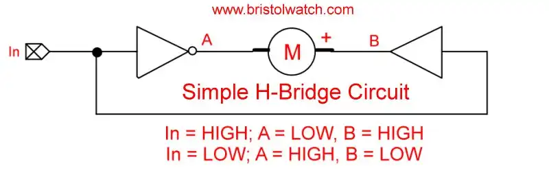
Fig. 9 Basic one-input H-Bridge
Fig 9 is a block diagram that combines the circuits in Fig. 7 and Fig. 8 into a basic H-bridge motor control.

- MOSFET-Transistor Drivers with TC4420 and TC4429, IGBTs, etc.
- Introduction TC4420-TC4429 MOSFET Drivers
- Use TC4420 MOSFET Driver for Simple H-Bridge Circuit
- TC4420 MOSFET Driver Various Circuits
- TC4420 MOSFET Driver Replacement Circuits
- Test Power MOSFET Transistors, IGBTs
- Insulated Gate Bipolar Transistor IGBT Circuits
- Issues on Connecting MOSFETs in Parallel
- TC4420 MOSFET Driver Replacement Circuits
- TB6600 Stepper Motor Driver with Arduino
- Interfacing Microcontrollers to CMOS and MOSFET Circuits
- Simplified CMOS-MOSFET H-Bridge Circuit
- Tri-State H-Bridge using CD4093B CMOS Circuit
- Common Collector Opto-Isolated Bipolar Transistor Switches
- Compare 2N3055 MJE10005 Transistor Power Switches
- Connecting PCF8574P GPIO Expander to Raspberry Pi
- Programming PCF8574P 8-bit I-O Expander with Arduino
- DS1307 RTC with a CD4040 as a Precision Time Base
- CD4040 12-stage Binary Counter with DS1307 RTC Time Base
- Pt. 1 Interfacing Microcontrollers to CMOS and MOSFET Circuits
- Pt. 2 Simplified CMOS-MOSFET H-Bridge Circuit
- Pt. 3 Tri-State H-Bridge using CD4093B CMOS Circuit
- Pt. 1 TB6600 Stepper Motor Driver with Arduino
- Pt. 2 Program TB6600 Stepper Motor Driver with Arduino
- TB6600 Stepper Motor Driver with Arduino
- Off Site:
- Web Master
- Tri-Cities VA-TN
- General Science
- Hobby Electronics
- US Constitution
- Christianity 101
- Religious Themes
© Copyright 2018 Lewis Loflin E-Mail