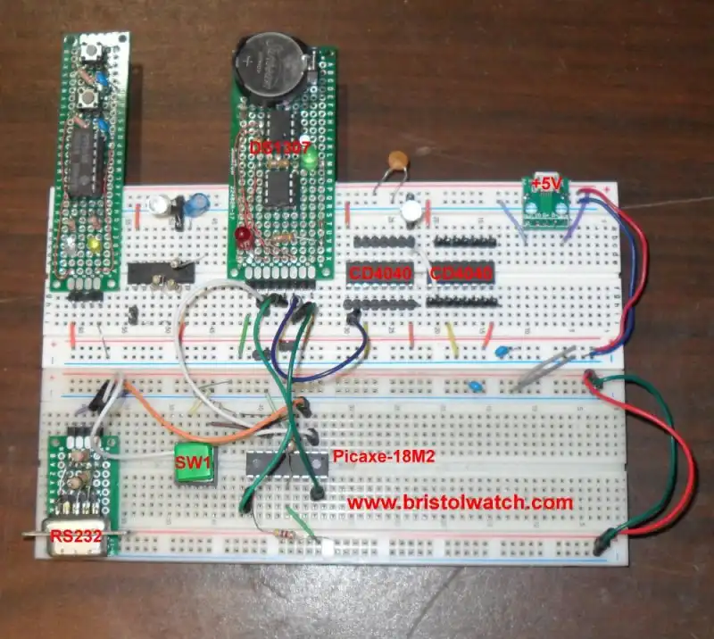
Fig. 1 PICAXE-18M2 on a breadboard with DS1307 RTC.
DS1307 RTC with a CD4040 as a Precision Time Base
by Lewis Loflin
The DS1307 real time clock is popular with hobbyists. Using the I2C protocol connections to an Arduino or PICAXE microcontroller is easy.
One function that gets little notice is the SQW or square wave output pin. This can be programmed to output a 32kHz, 8kHz, 4kHz, or 1 Hz.
My focus here is how to use this SQW output as a precision time base for external circuits. This is used with a CD4040 12-stage divider circuit.
Note that while this demo uses a PICAXE microcontroller it works the same way using Arduino or Raspberry Pi or whatever other UPC out there.
See:
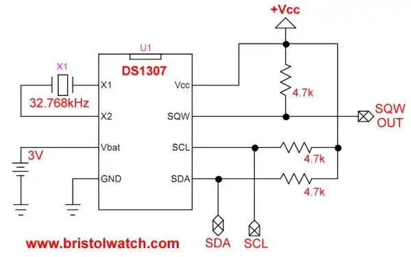
Fig. 2 My DS1307 clock schematic.
Here is the schematic of the DS1307 from Fig. 1. Because the SQW pin is open drain it must be pulled to +Vcc through a 4.7K resistor.
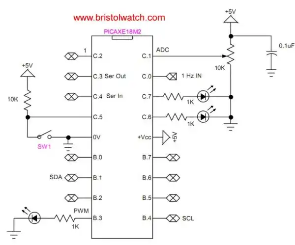
Fig. 3 PICAXE-18M2 schematic.
Fig. 3 is my PICAXE microcontroller connections. Besides the SDA and SDC connection I'll use pinC.0 connected to the 1Hz output from the DS1307 SWQ output or the Q12 output of a CD4040 12-Stage Ripple Carry Binary Counter. This assumes the SQW output of the DS1307 4096Hz input.
See CD4040 12-stage Binary Counter with DS1307 RTC Time Base.
My PICAXE control circuit uses 18M2. An Arduino, etc. could also be used.
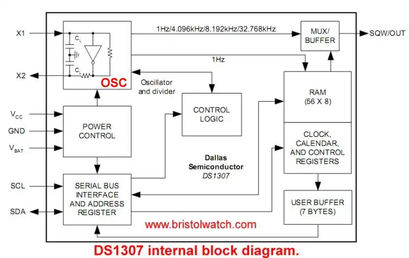
Fig. 4 DS1307 internal block diagram.
Fig. 4 illustrates the internal functional block diagram of the DS1307.
Here we focus on the crystal oscillator section and SQW output. By writing a single to register 0x07 one can turn the SQW output On-Off and select the frequency.
I assume the rest of the DS1307 is programmed as a real time clock. Accessing the SQW output does not change the function of the other registers.
See the DS1307 spec sheet ds1307.pdf
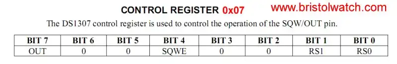
Fig. 5 DS1307 register 0x07.
Fig. 5 illustrates register 0x07. Bit if set HIGH turns on the SQW output, a LOW is Off. Bit 7 determines the HIGH or LOW on the SQW is turned off.
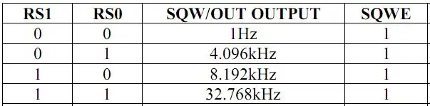
Fig. 6 Frequency output from DS1307 SQW based on bits RS0 and RS1.
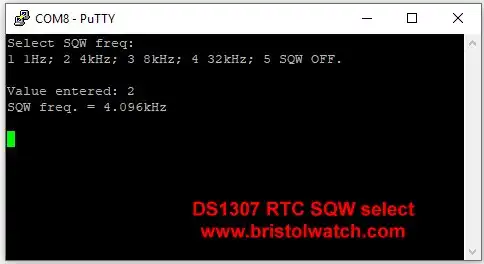
Fig 6 DS1307 SQW frequency select on a PuTTY terminal.
Fig. 6 uses a terminal to select the SQW output frequency.
Download the program ds1307s1.bas.
Press SW1 (Fig. 3) then select 1-5. Timeout is 5 seconds.
Below is a simple routine to write to DS1307 register 0x07. Select the value of temp for desired output.
; Use a DS1307 RTC
#picaxe 18m2 ; type chip used

symbol SW1 = pinC.5
symbol temp = b0

hi2csetup i2cmaster, %11010000, i2cslow, i2cbyte
; must shift address 1 bit left
; DS1307 setup address 0xB0

main:
if SW1 = 1  then goto main
temp = %00010001 ; 4,096 Hz
hi2cout $07,(temp)
goto main
Here are the values for temp:
temp = %00010000 ; 1 Hz
temp = (%00010001) ; 4,096 Hz
temp = (%00010010) ; 8,192 Hz
temp = (%00010011) ; 32,768 Hz
temp = (%10000000) ; OFF
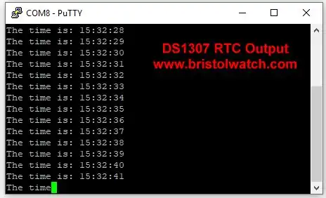
Fig. 7 DS1307 clock output on a terminal.
Time output from a DS1307 on a terminal. For this to work a 1Hz square wave must be input on pinC.0 (see Fig. 3).
This can be derived from the 1Hz output from the DS1307 SQW pin.
An alternate input can be derived from the Q12 pin of a CD4040 with and input to the CD4040 of 4,098 Hz. from the DS1307 SQW pin.
The clock program is downloaded at DS1307b.bas.
Because no good terminal program comes with Windows 10 I used PuTTY in the videos. To get PuTTY see www.putty.org. I use the stand alone EXE. My only interest is as an RS232 terminal though a com port. It is also free and open source.
Fig. 8 UGREEN USB to RS232 adaptor.
I used PuTTY with a UGREEN USB-to-RS232 adaptor on Windows 10. This allows me to get away from the PICAXE and Arduino serial monitors.
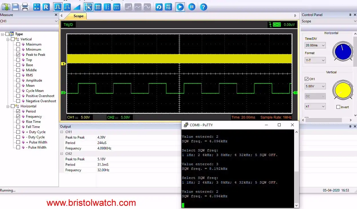
Fig. 9 USB oscilloscope output from a CD4040 frequency divider.
Click for larger image.
Full size image of above. See cd40.webp.
Fig. 9 is the output to my USB oscilloscope and the frequency select program for the DS1307 on PuTTY.
Channel 1 is the 4,096Hz output from the DS1307 as selected by the menu on PuTTY. Channel 2 is connected the Q7 (pin 4) of a CD4040 used as a frequency divider.
The oscilloscope is triggered on channel from the 32Hz output from pin 4.
For more in the CD4040 and related parts see CD4040 12-stage Binary Counter with DS1307 RTC Time Base

- MOSFET-Transistor Drivers with TC4420 and TC4429, IGBTs, etc.
- Introduction TC4420-TC4429 MOSFET Drivers
- Use TC4420 MOSFET Driver for Simple H-Bridge Circuit
- TC4420 MOSFET Driver Various Circuits
- TC4420 MOSFET Driver Replacement Circuits
- Test Power MOSFET Transistors, IGBTs
- Insulated Gate Bipolar Transistor IGBT Circuits
- Issues on Connecting MOSFETs in Parallel
- TC4420 MOSFET Driver Replacement Circuits
- TB6600 Stepper Motor Driver with Arduino
- Interfacing Microcontrollers to CMOS and MOSFET Circuits
- Simplified CMOS-MOSFET H-Bridge Circuit
- Tri-State H-Bridge using CD4093B CMOS Circuit
- Common Collector Opto-Isolated Bipolar Transistor Switches
- Compare 2N3055 MJE10005 Transistor Power Switches
- Connecting PCF8574P GPIO Expander to Raspberry Pi
- Programming PCF8574P 8-bit I-O Expander with Arduino
- DS1307 RTC with a CD4040 as a Precision Time Base
- CD4040 12-stage Binary Counter with DS1307 RTC Time Base
- Pt. 1 Interfacing Microcontrollers to CMOS and MOSFET Circuits
- Pt. 2 Simplified CMOS-MOSFET H-Bridge Circuit
- Pt. 3 Tri-State H-Bridge using CD4093B CMOS Circuit
- Pt. 1 TB6600 Stepper Motor Driver with Arduino
- Pt. 2 Program TB6600 Stepper Motor Driver with Arduino
- TB6600 Stepper Motor Driver with Arduino
- Off Site:
- Web Master
- Tri-Cities VA-TN
- General Science
- Hobby Electronics
- US Constitution
- Christianity 101
- Religious Themes
© Copyright 2018 Lewis Loflin E-Mail