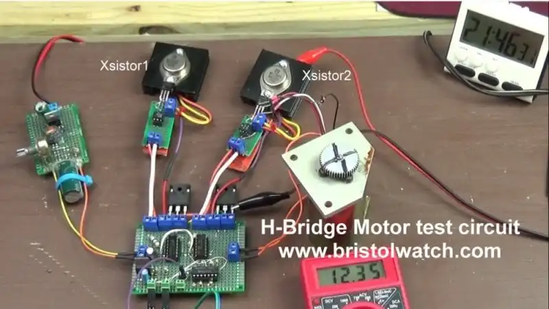
Fig. 1 H-Bridge motor control with IGBTs and bipolar transistors.
Common Collector Opto-Isolated Bipolar Transistor Switches
by Lewis Loflin
Earlier I presented several circuits related to a tri-state H-bridge motor controls. We used MOSFETs and CMOS integrated circuits.
The single largest headache was trying to use P-channel MOSFETs.
Also many microcontrollers produce insufficient output voltage to drive many MOSFETs.
For more on this see Basic Digital Circuits to H-Bridge Motor Controls.
Here I'm concerned with the "high-side" transistor driver circuits. They are Xsistor1, Xsistor2 shown in Fig. 1 above.
This with an opto-coupler the solved many problems. The culprit was P-channel gate-source MOSFET voltage limitations. This is usually 20V.
Much of that is covered in From Basic Digital Circuits to H-Bridge Motor Controls.
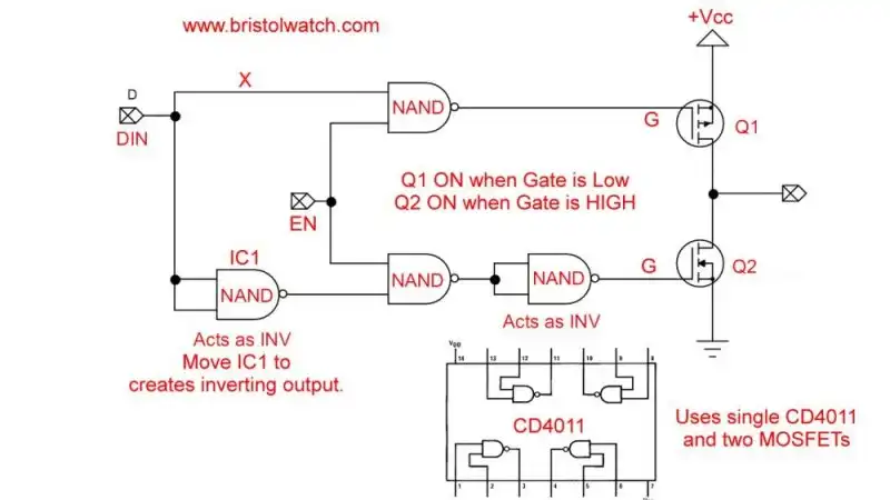
See this sample schematic and note Q1: Non-Inverting Tri-State switch. The use of a CD4011 allows easy use with 5-volt or 3.3-volt microcontroller. This also works with the low-current 3.3-volt output on a Raspberry Pi GPIO. This assumes +Vcc is 3.3 or 5 volts.
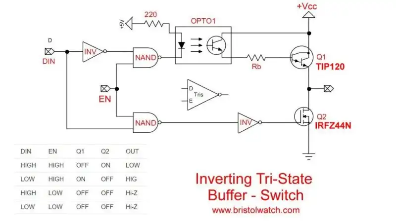
Fig. 2 Inverting Tri-State switch.
Note Fig. 2. I replaced Q1 p-channel MOSFET by a TIP120 NPN Darlington transistor.
I also used a 4N25 type optocoupler. This allows any motor voltage up to 55-volts. The design goal was 48-volts.
If the motor voltage is 24-volts a 4N25, etc. optocoupler is fine. For 48-volts use PC817 or similar optocoupler.
Here again I'm only concerned with Q1 and its associated optocoupler.
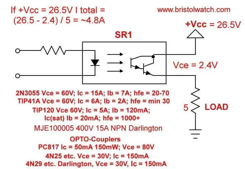
Fig. 3 generic opto-isolated high-side switch.
In Fig. 3 illustrates my generic device symbol.
The circuit incorporates some form of optocoupler and a Darlington bipolar output transistor.
In the series of tests +Vcc consisted of 2, 12-volt batteries in series.
When completely charged the output voltage was ~26.5-volts.
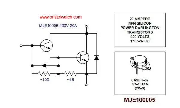
The load is 5-Ohms. The output Darlington transistor is aMJE100005 with these values.
The collector-emitter voltage drops ranged around 2-volts.
Also listed was the parts used in the tests.
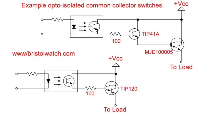
Fig. 4 Example opto-isolated high side transistor drivers.
Fig. 4 are the two circuits I used. The rest of this concerns the MJE10005 that was used in Fig. 1 and associated videos.
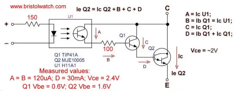
Fig. 5 MJE100005 opto-coupler driver.
Fig. 5 is the exact circuit used in Xsisotr1 and Xsistor2.
With a 5-Ohm load and +Vcc of 26.5-volts. The results of the test was interesting.
The circuit delivered a lot of current with excessive heat.
The collector-emitter voltage of Q4 must be at least 2.4-volts. The voltage Vbe supplies base current to Q2 through Q1.
The base-emitter voltage drops of the TIP41A (0.6V) and Q2 (1.6V) leaves 0.2V to produce base current for Q2.
In fact I removed Q1 and connected the emitter of U1 to the base of Q2 operation was almost identical.

- MOSFET-Transistor Drivers with TC4420 and TC4429, IGBTs, etc.
- Introduction TC4420-TC4429 MOSFET Drivers
- Use TC4420 MOSFET Driver for Simple H-Bridge Circuit
- TC4420 MOSFET Driver Various Circuits
- TC4420 MOSFET Driver Replacement Circuits
- Test Power MOSFET Transistors, IGBTs
- Insulated Gate Bipolar Transistor IGBT Circuits
- Issues on Connecting MOSFETs in Parallel
- TC4420 MOSFET Driver Replacement Circuits
- TB6600 Stepper Motor Driver with Arduino
- Interfacing Microcontrollers to CMOS and MOSFET Circuits
- Simplified CMOS-MOSFET H-Bridge Circuit
- Tri-State H-Bridge using CD4093B CMOS Circuit
- Common Collector Opto-Isolated Bipolar Transistor Switches
- Compare 2N3055 MJE10005 Transistor Power Switches
- Connecting PCF8574P GPIO Expander to Raspberry Pi
- Programming PCF8574P 8-bit I-O Expander with Arduino
- DS1307 RTC with a CD4040 as a Precision Time Base
- CD4040 12-stage Binary Counter with DS1307 RTC Time Base
- Pt. 1 Interfacing Microcontrollers to CMOS and MOSFET Circuits
- Pt. 2 Simplified CMOS-MOSFET H-Bridge Circuit
- Pt. 3 Tri-State H-Bridge using CD4093B CMOS Circuit
- Pt. 1 TB6600 Stepper Motor Driver with Arduino
- Pt. 2 Program TB6600 Stepper Motor Driver with Arduino
- TB6600 Stepper Motor Driver with Arduino
- Off Site:
- Web Master
- Tri-Cities VA-TN
- General Science
- Hobby Electronics
- US Constitution
- Christianity 101
- Religious Themes
© Copyright 2018 Lewis Loflin E-Mail