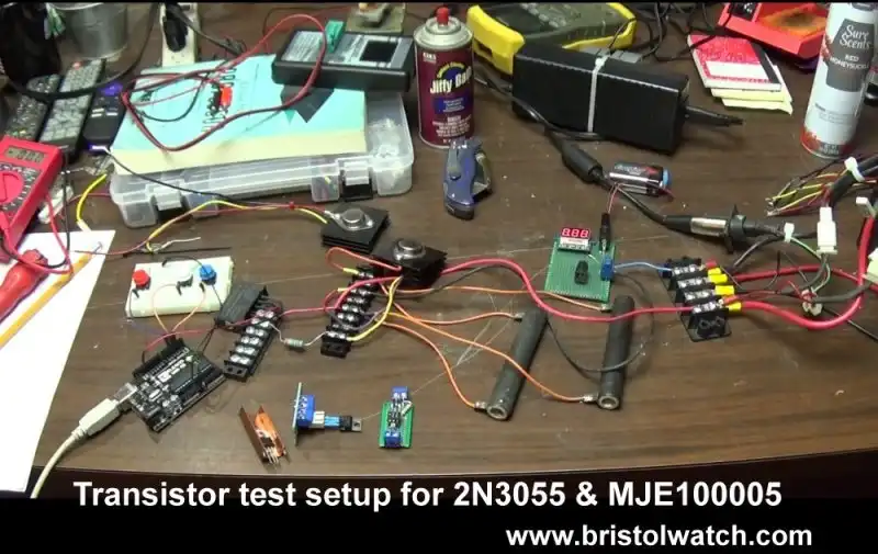
Fig. 1 Bipolar transistor test setup.
Compare 2N3055 MJE10005 Transistor Power Switches
by Lewis Loflin
I will compare the 2N3055 bipolar transistor to a MJE10005 power Darlington transistor.
While costing a little more the MJE100005 is superior in performance.
This will center on common emitter driver circuits.
Yes I know one can use MOSFETs. This is to learn transistor theory.

Fig. 2 Common emitter transistor switches circuits.
Fig. 2 illustrates common-emitter transistor switches. Both are power transistors.
The circuit on the left uses a TIP41A type transistor. On the right the circuits a TIP120 Darlington transistor.
Power transistors in general need higher drive currents. These small TO-220 style transistors could run into problems with Raspberry Pi GPIO.
To quote,
When the Pi was designed, they used a figure of 3mA per GPIO pins in determining if the regulator could supply enough current. Hence the simple 3mA limit mentioned before. However, if not all the pins are supplying current then you can divert those pin’s share of the current into the ones you are using. Hence the total recommended current limit of 17 * 3 = 51mA.
On Arduino the IO current is 40mA at 5V and 50mA at 3.3V.For an Arduino NANO 200mA max all pins.
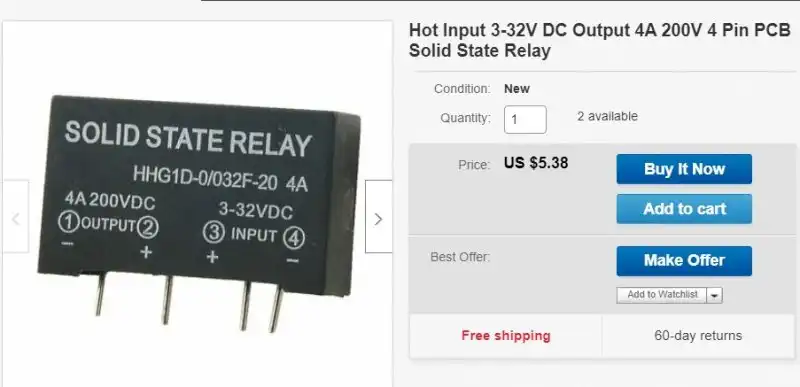
Fig. 3 Crydom PC board mount solid state relay.
Fig. 3 is a Crydom DC-DC solid-state relay. Its rating is 4-amps at 200-volts.
I happen to have several of these. This is not critical. I drove this from an Arduino Uno.
I also used a common-collector opto-isolator circuit. For more on that see Common Collector Opto-Isolated Bipolar Transistor Switches. These are a type of solid state relay but only work positive side of the load.
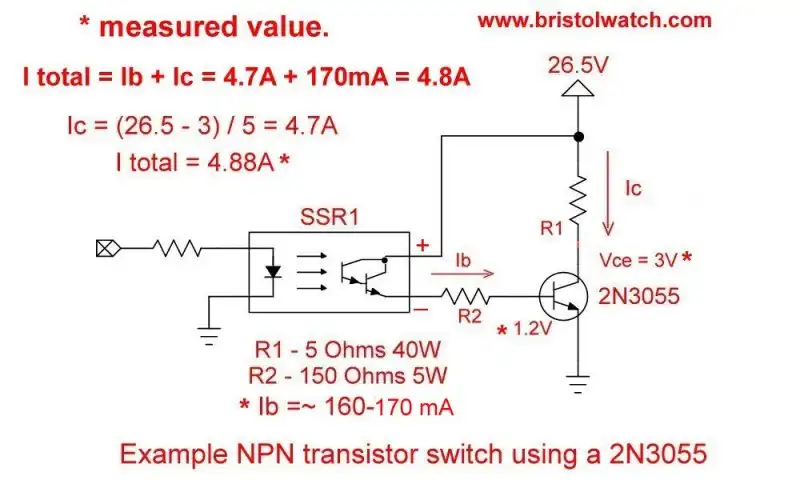
Fig 4 2N3055 common emitter power switch.
Fig. 4 uses a 2N3055. Base current (Ib) is from a 150-Ohm, 5-watt resistor. R1 is 5-Ohms, 40-watt.
Ib = 26.5 - 0.6 / 150 = ~160mA.
Collector current (Ic) = 26.5 - 3 / 5 = 4.7A. Total current (It) measured 4.8A.
Ib + Ic = It; 160mA + 4.7A = ~4.88A.
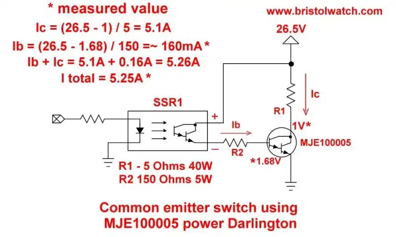
Fig. 5 MJE100005 common emitter power switch.
Fig. 5 is identical to the circuit in Fig. 4. A MJE10005 power Darlington transistor replaced the 2N3055.
Performance was much better. Collector-emitter voltage dropped from 3-volts to 1-volt.
Ic increased to 5.1A. Ib was much the same.
The MJE10005 has the extra advantage of an internal parasitic diode.

- MOSFET-Transistor Drivers with TC4420 and TC4429, IGBTs, etc.
- Introduction TC4420-TC4429 MOSFET Drivers
- Use TC4420 MOSFET Driver for Simple H-Bridge Circuit
- TC4420 MOSFET Driver Various Circuits
- TC4420 MOSFET Driver Replacement Circuits
- Test Power MOSFET Transistors, IGBTs
- Insulated Gate Bipolar Transistor IGBT Circuits
- Issues on Connecting MOSFETs in Parallel
- TC4420 MOSFET Driver Replacement Circuits
- TB6600 Stepper Motor Driver with Arduino
- Interfacing Microcontrollers to CMOS and MOSFET Circuits
- Simplified CMOS-MOSFET H-Bridge Circuit
- Tri-State H-Bridge using CD4093B CMOS Circuit
- Common Collector Opto-Isolated Bipolar Transistor Switches
- Compare 2N3055 MJE10005 Transistor Power Switches
- Connecting PCF8574P GPIO Expander to Raspberry Pi
- Programming PCF8574P 8-bit I-O Expander with Arduino
- DS1307 RTC with a CD4040 as a Precision Time Base
- CD4040 12-stage Binary Counter with DS1307 RTC Time Base
- Pt. 1 Interfacing Microcontrollers to CMOS and MOSFET Circuits
- Pt. 2 Simplified CMOS-MOSFET H-Bridge Circuit
- Pt. 3 Tri-State H-Bridge using CD4093B CMOS Circuit
- Pt. 1 TB6600 Stepper Motor Driver with Arduino
- Pt. 2 Program TB6600 Stepper Motor Driver with Arduino
- TB6600 Stepper Motor Driver with Arduino
- Off Site:
- Web Master
- Tri-Cities VA-TN
- General Science
- Hobby Electronics
- US Constitution
- Christianity 101
- Religious Themes
© Copyright 2018 Lewis Loflin E-Mail