PC Printer Port Arduino LCD Control Part 4
We now come to adding a 2 line by 16 character LCD display to our project. We have full read-write capability with Arduino now we can display results on the LCD display.
Even with all of these connections we still have 5 outputs and 4 inputs for additional uses. The LCD functions are as follows:
pulseCLK() used to clock data into the Sn74164.
pulseE() shifts the parallel data in the display. The RS pin determines if the data is a command/address or ASCII code.
ssrWrite(int) uses a "for" loop with pulsCLK() to shift 8-data into the SN74164.
initLCD(), clearLCD(), and Home() are used to setup the operation of the LCD display. They set RS LOW for command mode, use ssrWrite() to clock byte into 74164, the use pulseE() to enter parallel data into display control circuits.
gotoLocation(address) inputs an address in the internal ram of the display at a select location for display. 0x80 is column 0, line 0 (first character line 1) and 0xC0 is column 0 line 1 (first character line 2).
wrtiteString(text-string) is used with the above functions to write an ASCII string to the display. This must proceeded by gotoLocation(address) to set the position pointer in the display for the text.
convBinary(value) is used to convert an 16-bit number to an ASCII string of 1s and 0s. It doesn't drop leading 0s like the python bin(x) function does.
For the electrical connections see Controlling a Serial LCD Display on a PC Printer Port with Python
The function readDS18B20() not only prints the temperature readings on the terminal but on the LCD display.
- Project pages:
- Part 1: Read Arduino with PC Printer Port
- Part 2: Better way to Read Arduino Through the PC Printer Port
- Part 3: Read-Write an Arduino Through a PC Printer Port
- Part 4: Control LCD Display and Arduino from the PC Printer Port
To use this one must setup their PC to use my modified pyparallel. See Programming the PC Printer Port in Python.
- Arduino sketches needed by programs:
- pportArduino1.ino read only after reset.
- pportArduino2.ino reset once and multiple reads.
- pportArduino3.ino reset once read write Arduino infinite times - multiple commands.
- Related Raspberry Pi projects:
- Connect Serial LCD to Raspberry Pi
- Serial Read from Arduino to Raspberry Pi
- Arduino Raspberry Pi Interface with LCD Display
#!/usr/bin/env python
# File pportArduinoReadbitsLCD.py
# http://www.bristolwatch.com/pport/index.htm
# By Lewis Loflin - lewis@bvu.net
# Read serial data from Arduino
# Same as TLC548 except 16 bit.
# This version use Data port bits D0-D3
# Data from Arduino displayed on LCD and terminal.
# SW1 is connected from ground to DB25 pin 10 and pulled high
# by a 10k resistor.
# Reset used with Arduino sketch
# pportArduino1.ino for each read.
# Reset used once for pportArduino2.ino
# then multiple reads.
# pportArduino3.ino is setup for read/write.
# Write a code then read back result
# in some case original code.
# 0x5600 blink LED on DP13 returns 0x5600
# 0x5500 analogRead(0) returns 0-1023
# 0x5700 DS18B20 temp sensor return integer
# 0x58XX PWM DP9 - X being 0 to 255 in HEX.
# Arduino returns 0x58XX
import parallel
import time
p = parallel.Parallel()
############################LCD###########################
Line1 = 0x80 # location LCD row 0 col 0 or line 1
Line2 = 0xC0 # location LCD row 1 col 0 or line 2
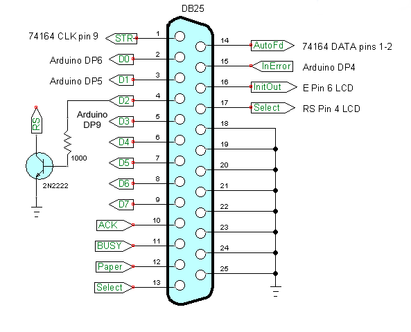
# Bit_out Pin 1-2 Sn74164
# CLK Pin 9 Sn74164 - clock bit - LOW to HIGH to LOW
# RS Pin 4 LCD - LOW command; HIGH ASCII
# E Pin 6 LCD - clock data into LCD - HIGH to LOW to HIGH
# init i/o pins
p.setDataStrobe(0) # Pin 1 use as CLK orange wire
p.setAutoFeed(0) # Pin 14 use as data bit for 74164 yellow
p.setInitOut(1) # Pin 16 use as E brown wire
p.setSelect(0) # Pin 17 use as RS white wire
p.getInError() # Pin 15 input to DATA OUT Arduino DP4
def pulseCLK():
p.setDataStrobe(1)
# time.sleep(.01)
p.setDataStrobe(0)
return
def pulseE():
p.setInitOut(0)
# time.sleep(.01)
p.setInitOut(1)
return
# MSB out first!
def ssrWrite(value):
for x in range(0,8):
temp = value & 0x80
if temp == 0x80:
p.setAutoFeed(1) # set data bit HIGH
else:
p.setAutoFeed(0)
pulseCLK()
value = value << 0x01 # shift left
time.sleep(.001)
p.setDataStrobe(0)
p.setAutoFeed(0)
return
def initLCD():
p.setSelect(0) # RS LOW
ssrWrite(0x38) # setup for 2 lines
pulseE()
ssrWrite(0x0F) # blinking cursor
pulseE()
clearLCD()
Home()
return
def clearLCD():
p.setSelect(0) # RS LOW
ssrWrite(0x01) # clear
pulseE()
return
def Home():
p.setSelect(0) # RS LOW
ssrWrite(0x02) # home
pulseE()
return
def gotoLocation(val):
p.setSelect(0) # RS LOW
#if val < 0x80:
# val = 0x80
ssrWrite(val)
pulseE()
return
def writeString(myString):
i = len(myString)
p.setSelect(1) # Pin 17 RS - HIGH is ASCII
for x in range(0,i):
y = ord(myString[x])
ssrWrite(y)
pulseE()
p.setSelect(0) # Pin 17 RS LOW
return
initLCD()
##################################################
# Reset Arduino to perform
# whatever reading if needed
# Delay 2 seconds after reset
def resetArduino():
writeD2(1)
time.sleep(.001)
writeD2(0)
time.sleep(2)
###############Connecting Arduino#################
# data LSB first
# enable CS1 HIGH
# set CLK HIGH
# read data bit shift left
# set CLK LOW
# repeat 15 times
# then once more after loop.
# last bit should not be shifted.
# Arduino
# define CLK 6
# define CS1 5
# define dataBit 4
# Pin 15 input to DATA OUT Arduino DP4
# Connect pport pin 2 to Arduino CLK DP6
def writeD0(bit_val):
if bit_val == 1:
p.setData(p.data() | 1) # set bit 0
else: # clear bit 0
p.setData(p.data() & (255 - 1))
return
# Connect pport pin 3 to Arduino CS1 DP5
def writeD1(bit_val):
if bit_val == 1:
p.setData(p.data() | 2) #set bit 1
else: # clear bit 1
p.setData(p.data() & (255 - 2))
return
# Connect pport pin 4 to Arduino Reset
def writeD2(bit_val):
if bit_val == 1:
p.setData(p.data() | 4) #set bit 1
else: # clear bit 1
p.setData(p.data() & (255 - 4))
return
# Connect pport pin 5 to Arduino DP2
def writeD3(bit_val):
if bit_val == 1:
p.setData(p.data() | 8) #set bit 1
else: # clear bit 1
p.setData(p.data() & (255 - 8))
return
# init Arduino:
writeD0(0) # Arduino DP6 CLK for read data for write
writeD1(0) # Arduino CS1 DP5
writeD2(0) # Arduino Reset
writeD3(0) # Arduino DP2 IRQ CLK for write
#################Write Arduino#######################
# MSB out first!
def writeArduino(value):
writeD3(1) # tell Arduino write is coming
writeD1(1) # CS1 HIGH
for x in range(0,15):
temp = value & 0x8000
if temp == 0x8000:
writeD0(1) # set data bit HIGH
else:
writeD0(0)
value = value << 0x01 # shift left
time.sleep(.001)
writeD3(0)
# time.sleep(.001)
writeD3(1)
temp = value & 0x8000
if temp == 0x8000:
writeD0(1)
else:
writeD0(0)
writeD1(0)
writeD3(0)
return
###################Read Arduino######################
def readArduino(delayT):
temp = 0
writeD1(1) # enable CS
time.sleep(delayT)
for i in range(0,15): # loop here 7 times
writeD0(1) # CLK HIGH
time.sleep(.001)
temp = temp + p.getInError() # get bit
temp = temp << 1 # shift 1 bit left
writeD0(0) # CLK LOW
writeD0(1) # CLK HIGH
time.sleep(.001)
temp = temp + p.getInError() # get bit 8
writeD0(0) # CLK LOW
writeD1(0) # CS LOW
return temp
#####################################################
# Print a 16-bit number (integer) in binary.
# Returns string.
# unlike python bin() this doesn't drop leading zeros
def convBinary(value):
binaryValue = 'b'
for x in range(0, 16):
temp = value & 0x8000
if temp == 0x8000:
binaryValue += '1'
else:
binaryValue += '0'
value = value << 1
return binaryValue
# SW1 is connected from ground to DB25 pin 10 and pulled high
# by a 10k resistor.
def SW1():
return p.getInAcknowledge()
# check pin 10 DB25 when pressed returns 0
def degC(val): # convert value DS18B20 read
return val * 0.0625
def degF(val): # convert value DS18B20 read
return (val * 0.0625) * 9 / 5 + 32
# 0x5600 blink LED 13
# 0x5500 analogRead(0)
# 0x5700 DS18B20 temp sensor
# 0x58XX PWM 0 - 255 pin 9 Arduino
#writeArduino(0x587f)
def readDS18B20():
gotoLocation(Line1)
writeString("Wait for T:")
print "Please wait for T reading..."
writeArduino(0x5700)
Treading = readArduino(.5) # delay .5 sec. DS18B20
print degC(Treading), "deg. C"
print degF(Treading), "deg. F"
gotoLocation(Line1)
writeString(str(degC(Treading)) + " deg. C")
gotoLocation(Line2)
writeString(str(degF(Treading)) + " deg. F")
return Treading
def readAnalog0():
writeArduino(0x5500)
return readArduino(.1)
# resetArduino()
for k in range(0,20):
j = readDS18B20()
print "Reading number ", k
print "j = ", hex(j), " in HEX."
print "j = ", convBinary(j), "in binary."
print "j = ", j, "in decimal."
time.sleep(5)
clearLCD()
print "Exit now."
exit
Download pport-1.0.iso from Sourceforge.com then burn to DVD (file size 920 meg.), insert into DVD drive and reboot. Make sure PC is set to boot from DVD ROM.
This is pre-configured by myself to use Python to control the printer port. Python can be run from IDLE or Geany.
All of my PPORT electronics projects will work without installation to a PC.
Programs can be saved to thumb drive in LIVE mode.
Projects
Below are listed a series of projects using pyparallel and electronics. Starting with routines I wrote to aid students I'd advise walking through this in sequence. Have fun and send comments and/or corrections to lewis@bvu.net.
- Introduction to Python Bitwise Operations
- Python Bitwise Operations by Example
- Using the PC Printer Port series:
- Programming the PC Printer Port in Python
- Additional Commands for Py-Parallel
- Controlling Data Bits on the PC Parallel Port
- Connecting Switches to the PC Printer Port with Python
- Reading an Analog Voltage Through the PC Printer Port Part 1
- Reading an Analog Voltage Through the PC Printer Port Part 2
- Controlling a Serial LCD Display on a PC Printer Port with Python
- Serial ADC and LCD Display with PC Printer Port with Python
- Controlling MAX7219 LED Display with PC Printer Port with Python
- MAX7219 8-Digit LED Display and Serial ADC in Python
- Project pages:
- Part 1: Read Arduino with PC Printer Port
- Part 2: Better way to Read Arduino Through the PC Printer Port
- Part 3: Read-Write an Arduino Through a PC Printer Port
- Part 4: Control LCD Display and Arduino from the PC Printer Port
- Arduino sketches needed by programs:
- pportArduino1.ino read only after reset.
- pportArduino2.ino reset once and multiple reads.
- pportArduino3.ino reset once read write Arduino infinite times - multiple commands.
- Related Raspberry Pi projects:
- Connect Serial LCD to Raspberry Pi
- Serial Read from Arduino to Raspberry Pi
- Arduino Raspberry Pi Interface with LCD Display
Linux Videos
- Live Linux Distro for Using Printer Port with Electronics
- Using the powerful Rox-Filer system in Linux
- Use FEH under Linux for a Wallpaper Setter
- How to create Symbolic links in Linux
- Printer Port Interfacing Videos:
- Connect Electronics to PC printer Port with Python
- Setup PC Printer Port with Python-Linux
- Use PC Printer Port to Read Analog Voltage
- Read-Write Arduino ADC PWN with Printer Port
- Printer Port to Serial LCD Display
- Connect Arduino to PC Printer Port for advanced control
Printer Port in C
- Exploring Digital Computer Electronics
- Hardware Review Connecting PC Parallel Ports
- Operation TB6600 Stepper Controller with PC Parallel Port
- Build or Buy Parallel Port Breakout Board?
- Build Serial HD44780 LCD Display Connect to Parallel Port
- Motherboards
- Presario 1999 CM1001 Gaming Computer Salvage
- Live Test 2002 VIA EPIA-800 Mini ITX Motherboard
- Salvage, Test 2012 AAEON EMB-B75A Industrial Motherboard
- Web Master
- Gen. Electronics
- YouTube Channel
- Arduino Projects
- Raspberry Pi & Linux
- PIC18F2550 in C
- PIC16F628A Assembly
- PICAXE Projects
Web site Copyright Lewis Loflin, All rights reserved.
If using this material on another site, please provide a link back to my site.