
Fig. 1 TB6600 stepper motor controller.
Connection-Operation TB6600 Stepper Controller with PC Parallel Port
The TB6600 is a cheap stepper motor controller available in Ebay for about $10. It is single axis and operates bipolar stepper motors from 9-volts to about 40-volts at about 4 amps.
I did two videos and a webpage on using the TB6600 with an Arduino microcontroller. Here I will use this with a PC parallel or printer port.
See the links below for the earlier videos and Arduino.
Using the TB6600 with Arduino:
- TB6600 Stepper Motor Controller Arduino Part 1 Youtube
- TB6600 Stepper Motor Controller Arduino Part 2 Youtube
- TB6600 Stepper Motor Driver with Arduino
The goals are as follows:
1) a deeper look at the wiring and connections of the TB6600;
2) demonstrate the use a the parallel port a true 8-bit hardware port;
3) demonstrate the bit manipulations using bitwise operators under C.
Fig. 1 above illustrates the TB6600. It has three control connections (enable, count, direction), four connections for a bipolar stepper motor, and six setup micro switches.
Three of the setup switches select the current limit. The other setup micro-stepping. These will be explained next three slides.
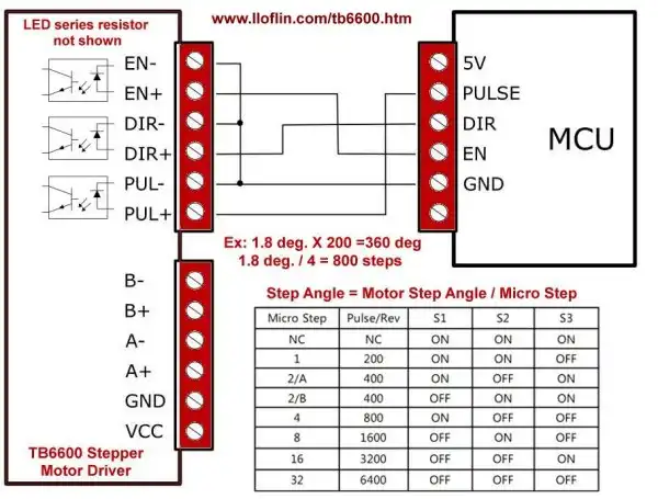
Fig. 2 TB6600 stepper motor controller micro-stepping switches.
Micro-Stepping Setup, Common Ground Connections
Let's look at Fig. 2. Note the three control connections for micro-stepping. S1, S2, and S3 are step multipliers for 360 degrees.
For example my motor in the video was 7.5 degrees per step or 48 steps for 360 degrees. A 1.8 degree per step motor requires 200 steps for 360 degrees.
Setting the switches divides the step angel, not the number of steps. Using 4 as an example, dividing 7.5 degrees by 4 = 1.875 degrees per step or 196 steps for 360 degrees.
In the case of the 1.8 degree per step motor, 800 steps are required for 360 degrees.
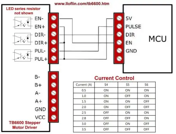
Fig. 3 TB6600 stepper motor controller current limit switches.
Current Limiting
The TB6600 also has built in current limiting which makes motor voltage easier to deal with.
For example I have 5-volt 1-amp stepper motor. Setting switches S4, S5, and S6 to 0.5 amp or 1 amp assures say a 12-volt power (with the correct current rating) can drive the 5-volt motor.
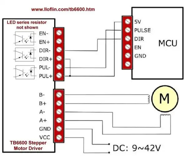
Fig. 4 TB6600 stepper motor controller basic electrical connections.
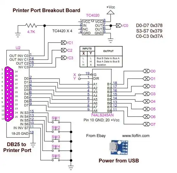
Fig. 5 Home built parallel breakout board.
Connections and Operation
Fig. 5 is my parallel port breakout board. The actual electrical connections I use is Fig. 2. Or you can buy a CNC parallel port breakout board to do much the same thing.
Power (5-volts) in both cases is derived from a USB port.
See the following:
PC printer port base address is 0x378. This is 8-bit bi-directional. Buffered by 74LS245 set for output. 74LS245 DIR pin 1 HIGH, enable pin 19 OE LOW.
PPORT pins 2-9 (DB25 connector) to 74LS245 pins A1-A8. Output B1-B8 is D0-D7. See spec sheet. Wired with common ground.
T6600 stepper motor controller: PUL+ to PPORT D0, PUL- GRD; Pulse is LOW-HIGH-LOW.
DIR+ to PPORT D1, DIR- GND. D1 HIGH CW; D1 LOW CCW.
ENA+ to PPORT D2, ENA- GRD. D2 HIGH motor off, D2 LOW motor on. If ENA not connected motor on all times. Motor will be locked, can get hot. Thus ENA LOW locks motor until pulse.
Test Software
Download test software tb6600.txt
- Hobby Electronics Home Page
- Donate
- Exploring Digital Computer Electronics
- Hardware
- Hardware Review Connecting PC Parallel Ports
- Operation TB6600 Stepper Controller with PC Parallel Port
- Build or Buy Parallel Port Breakout Board?
- Build Serial HD44780 LCD Display Connect to Parallel Port
- Motherboards
- Presario 1999 CM1001 Gaming Computer Salvage
- Live Test 2002 VIA EPIA-800 Mini ITX Motherboard
- Salvage, Test 2012 AAEON EMB-B75A Industrial Motherboard
View all of my You Tube Videos
Also visit and subscribe to My YouTube Channel
- Main Light Fast Linux Desktops with Openbox, JWM
- Test Reuse Surplus PC Power Supplies
- Add WBAR Launch Dock to Raspberry Pi
- Add MPG123 Terminal Music Player to Raspberry Pi, Linux
- Basics of Alsamixer Audio Control for Linux
- Add Solid State Hard Drive to Raspberry Pi
- Beep a PC Speaker Add Beeper to Raspberry Pi
- Using FEH Wallpaper Setter Under Linux
- Scrot Lite Weight Screen Shot Software for Linux
- Using Light Weight Beaver Text Editor
- Install Viewnior Image Viewer for Linux
- Zmixer ALSA Sound Control Tutorial
- Tutorial Xinitrc Desktop Manager Control for Linux
- Setup Raspberry Pi Using JWM Window Manager
- Off Site:
- Web Master
- Tri-Cities VA-TN
- General Science
- Hobby Electronics
- US Constitution
- Christianity 101
- Religious Themes
Web site Copyright Lewis Loflin, All rights reserved.
If using this material on another site, please provide a link back to my site.