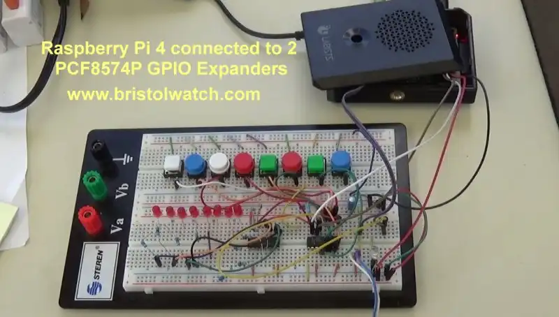
Fig. 1 Raspberry Pi 4 connected to 2 PCF8574P GPIO expanders.
Connecting PCF8574P GPIO Expander to Raspberry Pi
by Lewis Loflin
Here I'll connect the PCF8574P (above) GPIO expander to a Raspberry Pi. To cover the basic operation of the PCF8574P see Programming PCF8574P 8-bit I-O Expander with PICAXE, Arduino.
I'll connect 8 LEDs to one PCF8574P and 8 switches on another. We will read the switches then alter the LEDs, etc.
Only four connections besides power, ground are used on the Raspberry Pi. The PCF8574P is an I2C device using GPIO-2 (SDA) and GPIO-3 (SCL). A push button switch to ground from GPIO-21. GPIO-20 connected to the interrupt pin of one PCF8574Ps.
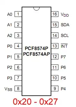
Fig. 2 PCF8574P pin connections.
Fig. 2 illustrates the pin connections of the PCF8475P.

Fig. 3 PCF8574P connected to 8 LEDs.

Fig. 4 PCF8574P connected to 8 switches.
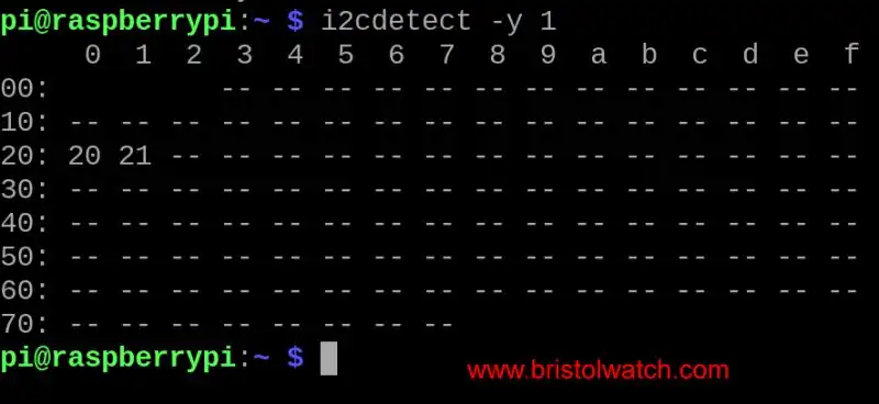
Fig. 5 PCF8574P device addresses with i2cdetect.
Demo 1
Connect switch from GPIO-21 to GND. GPIO-20 not used. A FOR loop counts from 0-256, uses an XOR to invert bits, then writes value to U1.
Program will either time out or pressing SW in GPIO-21 terminates program regardless of count.
#!/usr/bin/env python
# File picount_sw.py
# By Lewis Loflin - lewis@bvu.net
# uses 2 PCF8574P I2C 8-bit GPIOs
# Count 0-256 on 8 LEDs
# Press sw terminates count

# External module imports
import smbus
import time as t
import RPi.GPIO as GPIO

bus = smbus.SMBus(1)

# PCF8574P device addresses
U1 = 0x20 # 8 LEDs
U2 = 0x21 # 8 switches

# use BCM channel numbers
GPIO.setmode(GPIO.BCM)
# use GPIO 20, 21

int_pin = 20 # not used here
GPIO.setup(int_pin, GPIO.IN)
sw = 21 # to GND
GPIO.setup(sw, GPIO.IN, pull_up_down=GPIO.PUD_UP)

def writeVal(value):
    bus.write_byte(U1, value)
    return 0

def readVal():
    num1 = bus.read_byte(U2)
    return num1

for x in range(0,256):
    if GPIO.input(sw) == 0:
        break # end loop
    print x
    # XOR inverts bits
    x = x ^ 0xFF
    writeVal(x)
    #delay 200 mSec.
    t.sleep(.2)

# turn LEDs off
writeVal(0xFF)
GPIO.cleanup()
print "Good by!"
exit
Demo 2
If a switch is pressed on U2 write value to U1. If no switch pressed don't write to U1. If switches P0 and P1 are pressed together exit program.
#!/usr/bin/env python
# File pcf8574_demo2.py
# By Lewis Loflin - lewis@bvu.net
# uses 2 PCF8574P I2C 8-bit GPIOs

# module imports
import smbus
import time as t

# use BCM channel numbers
GPIO.setmode(GPIO.BCM)

# connect I2C
bus = smbus.SMBus(1)

# PCF8574P device addresses
U1 = 0x20 # 8 LEDs
U2 = 0x21 # 8 switches

# LEDs OFF
bus.write_byte(U1, 0xFF)

# switch pull ups on
bus.write_byte(U2, 0xFF)

def writeVal(num0):
    bus.write_byte(U1, num0)
    return 0

def readVal():
    num1 = bus.read_byte(U2)
    return num1

temp = 0
while (temp != 3):
    temp = readVal()
    if temp != 0xFF:
        writeVal(temp)
        # delay 200 mSec.
        t.sleep(.2)

# turn LEDs off
writeVal(0xFF)
GPIO.cleanup()
print "Good by!"
exit
Demo 3
Connect U2 INT pin to GPIO-21. Connect a switch from GPIO-20 to GND. Check for interrupt from U2, read U2 write value to U1.
The PCF8574P interrupt is interrupt on change, thus a key press generates 2 interrupts. Ignore 2nd interrupt which returns 0xFF.
#!/usr/bin/env python
# File picount_int.py
# By Lewis Loflin - lewis@bvu.net
# uses 2 PCF8574P I2C 8-bit GPIOs
# External module imports
import smbus # I2C
import time as t
import RPi.GPIO as GPIO

bus = smbus.SMBus(1)

# PCF8574 device addresses
U1 = 0x20 # 8 LEDs
U2 = 0x21 # 8 switches

# use BCM channel numbers
GPIO.setmode(GPIO.BCM)

# use GPIO 20, 21
int_pin = 20
GPIO.setup(int_pin, GPIO.IN)
sw = 21
GPIO.setup(sw, GPIO.IN, pull_up_down=GPIO.PUD_UP)

def writeVal(value):
    bus.write_byte(U1, value)
    return 0

def readVal():
    num1 = bus.read_byte(U2)
    return num1

def pcf8574_bits():
	temp = readVal()
	if temp == 255:
		return 0
	writeVal(temp)
	return 0

writeVal(0xFF) # turn LEDs off

while (GPIO.input(sw) == 1 ):
	# check for sw pressed
	if GPIO.input(int_pin) == 0:
		pcf8574_bits()
		t.sleep(.3)

# turn LEDs off
writeVal(0xFF)
GPIO.cleanup()
print "Good bye!"
exit

- MOSFET-Transistor Drivers with TC4420 and TC4429, IGBTs, etc.
- Introduction TC4420-TC4429 MOSFET Drivers
- Use TC4420 MOSFET Driver for Simple H-Bridge Circuit
- TC4420 MOSFET Driver Various Circuits
- TC4420 MOSFET Driver Replacement Circuits
- Test Power MOSFET Transistors, IGBTs
- Insulated Gate Bipolar Transistor IGBT Circuits
- Issues on Connecting MOSFETs in Parallel
- TC4420 MOSFET Driver Replacement Circuits
- TB6600 Stepper Motor Driver with Arduino
- Interfacing Microcontrollers to CMOS and MOSFET Circuits
- Simplified CMOS-MOSFET H-Bridge Circuit
- Tri-State H-Bridge using CD4093B CMOS Circuit
- Common Collector Opto-Isolated Bipolar Transistor Switches
- Compare 2N3055 MJE10005 Transistor Power Switches
- Connecting PCF8574P GPIO Expander to Raspberry Pi
- Programming PCF8574P 8-bit I-O Expander with Arduino
- DS1307 RTC with a CD4040 as a Precision Time Base
- CD4040 12-stage Binary Counter with DS1307 RTC Time Base
- Pt. 1 Interfacing Microcontrollers to CMOS and MOSFET Circuits
- Pt. 2 Simplified CMOS-MOSFET H-Bridge Circuit
- Pt. 3 Tri-State H-Bridge using CD4093B CMOS Circuit
- Pt. 1 TB6600 Stepper Motor Driver with Arduino
- Pt. 2 Program TB6600 Stepper Motor Driver with Arduino
- TB6600 Stepper Motor Driver with Arduino
- Off Site:
- Web Master
- Tri-Cities VA-TN
- General Science
- Hobby Electronics
- US Constitution
- Christianity 101
- Religious Themes
© Copyright 2018 Lewis Loflin E-Mail