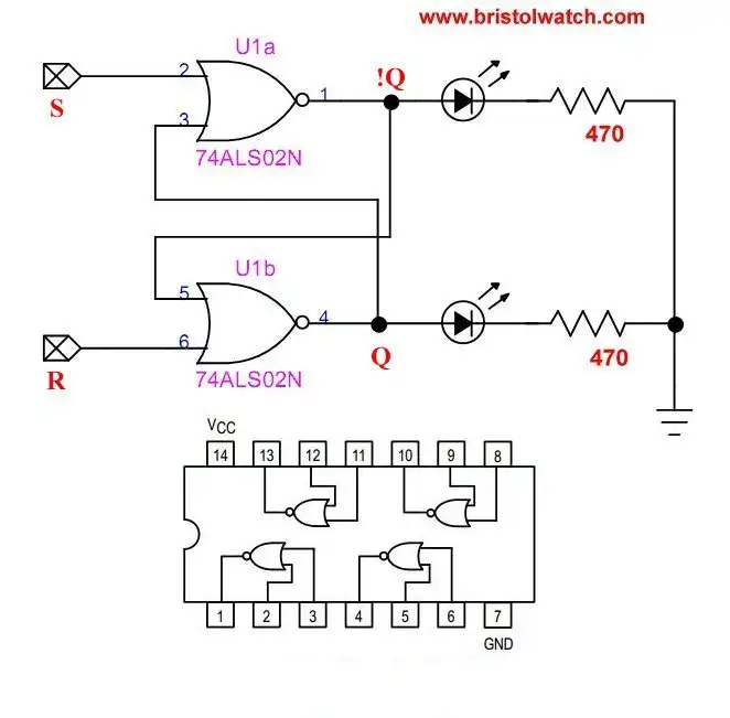
Fig. 1 SN74LS02 based SR latch.
Tutorial OR-NOR Circuits Including Monostable Multivibrator
Here I will look at several SN7402 circuits and NOR-OR gates in general. The SN7402 is a quad, 2-input NOR gate. I'll construct NOR gate based digital latch and a monostable multivibrator.
Fig. 1 is a basic Set-Reset (SR) latch. This also includes the pin connections in a 14-pin dual inline package.
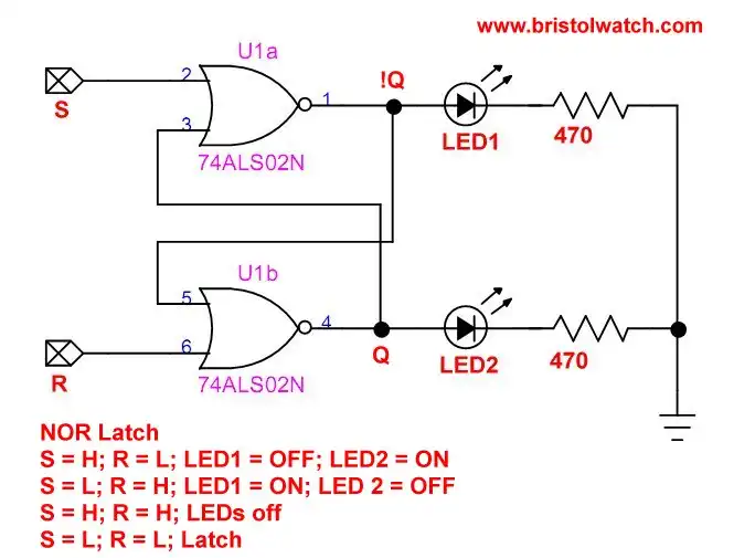
Fig. 2 SN74LS02 based SR latch.
Fig 2 is a basic SR latch. The truth table is as follows:
S = HIGH; R = LOW; Q = HIGH; !Q = LOW
S = LOW; R = HIGH; Q = LOW; !Q = HIGH
S = HIGH; R = HIGH; illegal Q and !Q LOW
S = LOW; R = LOW; latch
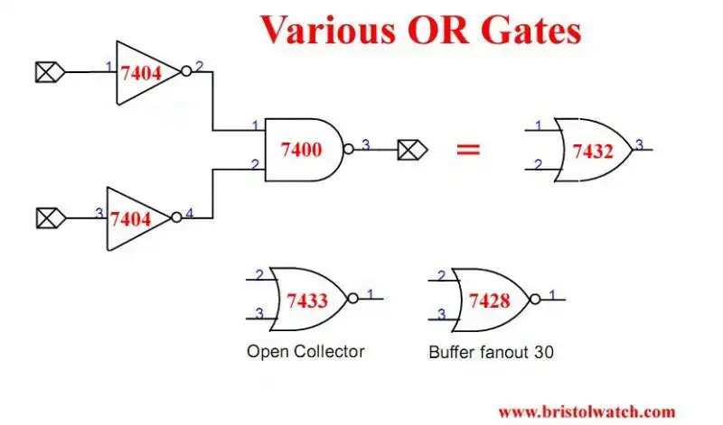
Fig. 3 Various other OR-NOR gates.
Fig. 3 illustrates other OR-NOR gates. Using a single SN7400 NAND gate and two SN7404 inverters used to construct an equivalent OR gate.
A SN7433 with an open collector output NOR gate. The SN7428 buffer or driver NOR gate.
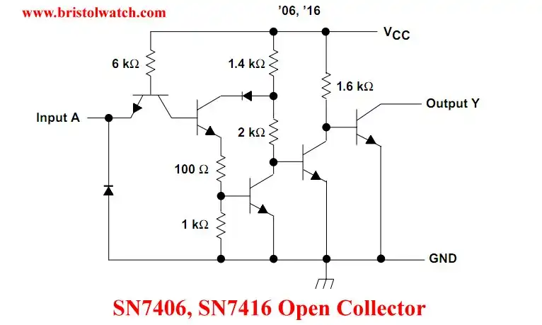
Fig. 4 SN7406 open collector diagram.
Fig. 4 illustrates a typical open collector output.
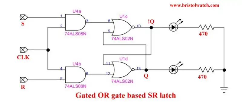
Fig. 5 Gated NOR gate based SR latch.
Fig. 5 is a gated SR latch. By using two SN7408 AND gates allow a set-reset condition during as positive going clock pulse. That doesn't fix the problem of the illegal S and R both HIGH condition.
Another possible variation is use two SN7400 NAND gates. That would reverse the Q and !Q outputs.
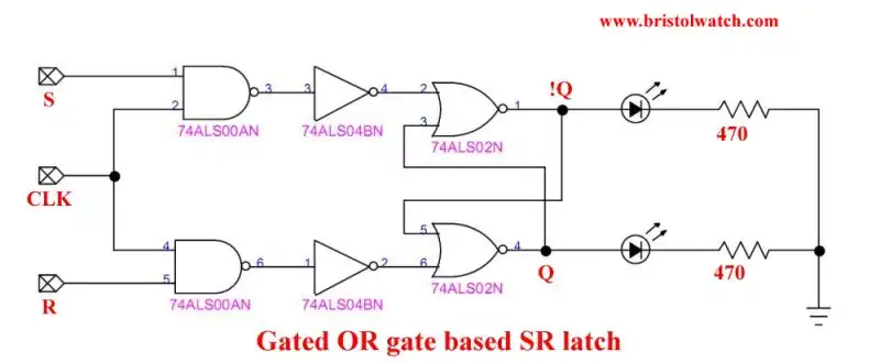
Fig. 6 Another variation Gated SN7402 NOR gate based SR latch.
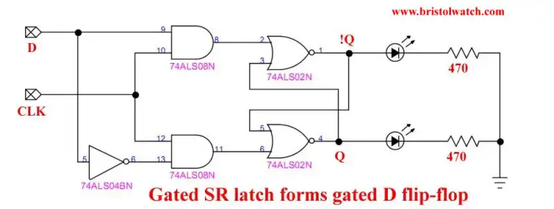
Fig. 7 Gated D flip-flop SN7402 based circuit.
Gated D flip-flop SN7402 based circuit. By adding a single SN7404 inverter creates a gated D flip-flop. The solves the illegal S HIGH, R HIGH condition.
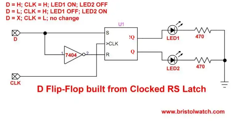
Fig. 8 Basic gated D flip-flop.
A D flip-flop is a building block for multi bit latches and shift registers.
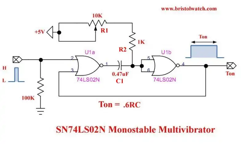
Fig. 9 SN7402 based monostable multivibrator.
Fig 9 illustrates a SN7402 based monostable multivibrator. A positive going trigger pulse creates a HIGH output. The time of Ton is based on the combination of (R1 + R2) * C1 * 0.6. Other literature says 0.7, but my tests show 0.6 is more accurate based on using a SN74LS02 and a SN74HC02.
I used this circuit as an AC power control test circuit just as I used a LM555 timer circuit. See LM555-NE555 One-Shot Multivibrator AC Power Control.
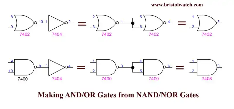
Fig. 10 -Build AND-OR gates from NAND-NOR gates.
- Quick navigation of this website:
- Basic Electronics Learning and Projects
- Basic Solid State Component Projects
- Arduino Microcontroller Projects
- Raspberry Pi Electronics, Programming
- Digital Circuits:
- Simple Schmitt Trigger SN74HC14 Square Wave Generator
- Introduction to RC Differentiator Circuits and Uses
- SN74HC14 Square Wave Generator uses SN7476 JK Flip-Flop
- SN74C14 Three Output Pulse Generator Circuit
- Astable CD4047 Geiger Counter Power Supply
- CD4047 Monostable Multivibrator Circuit
- Basic TTL Tri-State Buffer Circuit Examples
- Tutorial NOR Gate SR Latch Circuits
- Tutorial NAND Gate SR Latch Circuit
- Tutorial OR-NOR Circuits Including Monostable Multivibrator
- Brief Tutorial of XOR and XNOR Logic Gates
- LM555-NE555 One-Shot Multivibrator AC Power Control
- YouTube:
- Three Output Digital Pulse Generator
- Digital Circuits:
- Two Transistor LED Flasher Circuit
- Astable CD4047 Geiger Counter Power Supply
- CD4047 Monostable Multivibrator Circuit
- Basic TTL Tri-State Buffer Circuit Examples
- Tutorial NOR Gate SR Latch Circuits
- Tutorial NAND Gate SR Latch Circuit
- Coils for Highly Selective Crystal Radio
- Neon (NE-2) Circuits You Can Build
- Understanding Xenon Flashtubes and Circuits
Web site Copyright Lewis Loflin, All rights reserved.
If using this material on another site, please provide a link back to my site.