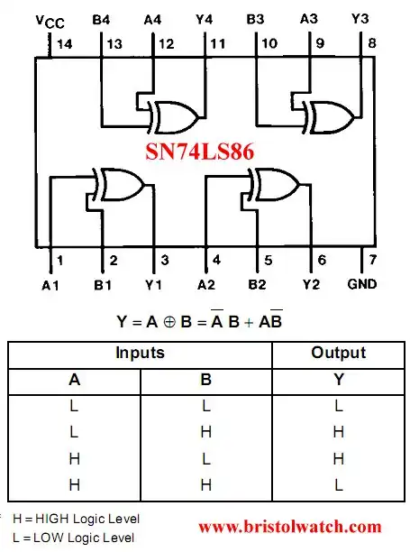
Fig. 1 DM74LS86N pin connections and truth table.
Brief Tutorial of XOR and XNOR Logic Gates
An Exclusive OR gate (XOR or EOR) is a digital gate that outputs a HIGH or TRUE logic level when two inputs, A and B, are different logic levels. Another variation is a Exclusive NOR that differs only with an inverted output. The output is LOW or FALSE when the inputs differ.
XOR gates are used to implement binary addition, subtraction, etc. They are of limited use with a microcontroller in external circuits. There are bitwise XOR functions used in programming. For example in Arduino this is used to invert bits useful for I-O ports. For example to toggle a LED connected to an I-O pin:
/*
  Blink LED PIN13 with XOR write directly to port.
  502 bytes. Empty setup and loop 444 bytes
  Total program size 58 bytes from 628 bytes!
  Won't compile error on Arduino-1.6.7-windows on XP
 */

 // Total program size 58 bytes from 628 bytes!
void setup() {
  DDRB = 0b00100000;  // 4 bytes
  PORTB = 0x00; // 2 bytes
}

void loop() {
  // XOR PORTB with 0x20 toggles bit B.5 aka DP13
  PORTB = PORTB ^ 0b00100000; // 8 bytes

  for (int i = 0; i <= 500; i++)   {
  // 1000 uSec = 1 mS
  delayMicroseconds(1000); // 26 bytes
  } // for loop 18 bytes
} // end loop
That is the reason I'm reviewing many basic digital circuits. It will enable on to better understand how program external hardware with a microcontroller. In the case above a bitwise XOR any bit XORed with 1 will be inverted in on pass. In reality the NOT (!) function seems too also be an XOR with 1 internally within the compiler.
For more on this subject see Arduino Blink LED Tutorial.
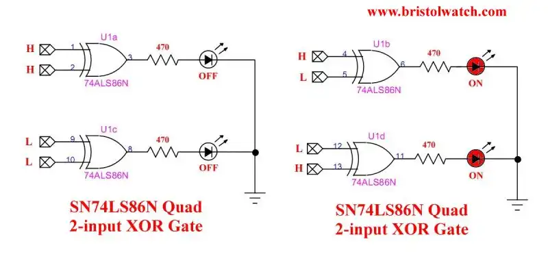
Fig. 2 - 74LS86 connections with LEDs.
Fig. 2 illustrates the electrical connections for the 74LS86 quad two-input XOR gate. The LEDs are ON only when the inputs differ. If one of the input pins is held HIGH or TRUE the state of the other pin HIGH or LOW will be inverted on the output. Thus any value be it a bit or 8-bits when XORed with a corresponding HIGH or binary 1 the output will be inverted.
The following three slides show how to construct an XOR or XNOR gate using other basic digital logic integrated circuits. There are many combinations.
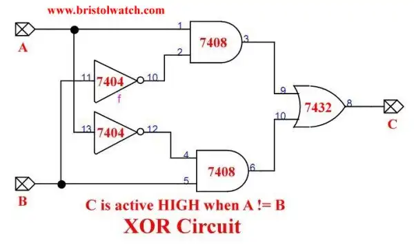
Fig. 3 - XOR gate built from 2 AND gates, 2 inverters, and an OR gate.
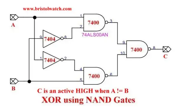
Fig. 4 - XOR gate built from three 7400 NAND gates and 2 7404 inverters.
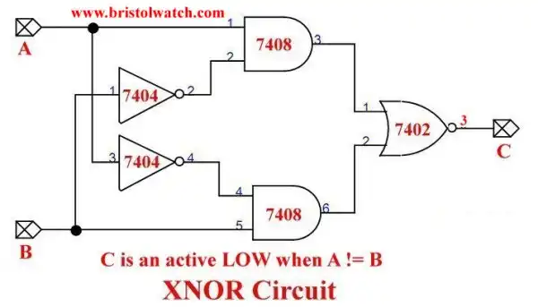
Fig. 5 -XNOR gate built from 2 7400 inverters, 2 7408 AND gates, and a 7402 NOR gate.
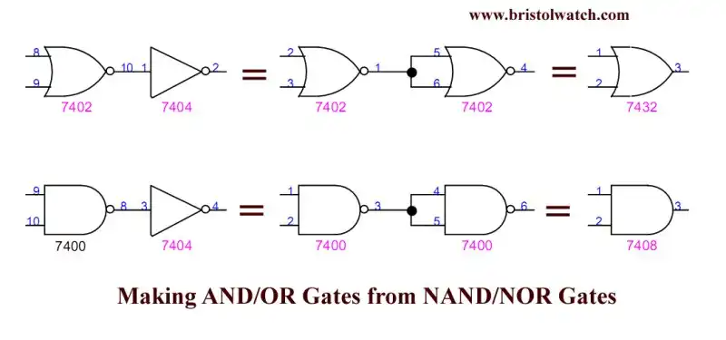
Fig. 6 -Build AND-OR gates from NAND-NOR gates.
- Quick navigation of this website:
- Basic Electronics Learning and Projects
- Basic Solid State Component Projects
- Arduino Microcontroller Projects
- Raspberry Pi Electronics, Programming
- Digital Circuits:
- Simple Schmitt Trigger SN74HC14 Square Wave Generator
- Introduction to RC Differentiator Circuits and Uses
- SN74HC14 Square Wave Generator uses SN7476 JK Flip-Flop
- SN74C14 Three Output Pulse Generator Circuit
- Astable CD4047 Geiger Counter Power Supply
- CD4047 Monostable Multivibrator Circuit
- Basic TTL Tri-State Buffer Circuit Examples
- Tutorial NOR Gate SR Latch Circuits
- Tutorial NAND Gate SR Latch Circuit
- Tutorial OR-NOR Circuits Including Monostable Multivibrator
- Brief Tutorial of XOR and XNOR Logic Gates
- LM555-NE555 One-Shot Multivibrator AC Power Control
- YouTube:
- Three Output Digital Pulse Generator
- Digital Circuits:
- Two Transistor LED Flasher Circuit
- Astable CD4047 Geiger Counter Power Supply
- CD4047 Monostable Multivibrator Circuit
- Basic TTL Tri-State Buffer Circuit Examples
- Tutorial NOR Gate SR Latch Circuits
- Tutorial NAND Gate SR Latch Circuit
- Coils for Highly Selective Crystal Radio
- Neon (NE-2) Circuits You Can Build
- Understanding Xenon Flashtubes and Circuits
Web site Copyright Lewis Loflin, All rights reserved.
If using this material on another site, please provide a link back to my site.