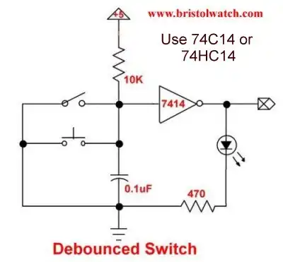
Fig. 1 SN74HC14N based debounced switch.
Three Output Pulse Generator Circuit for Digital Circuits
Make sure to use a SN74C14 or SN74HC14.
In digital circuits mechanical switch produce contact electrical noise that can cause erratic circuit behavior. This can be solved with software that slow down response and may not work, or can be solved by electrics.
Fig. 1 is a typical electronics solution. By using a SN74HC14 Schmitt trigger inverter with a RC circuit we have a clean digital pulse when a switch is pressed. A 7414 has six inverters in a 14-pin DIP package and cost about 50 cent.
Here I'll go beyond a mere debounced switch to create three output pulses including very narrow pulses. This will be used in upcoming digital circuits experiments in this series.
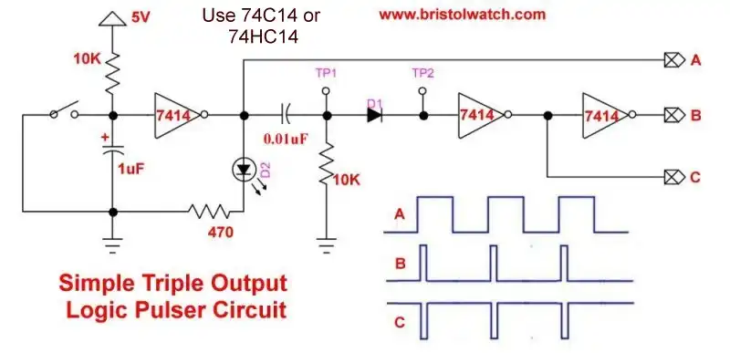
Fig. 2 SN74HC14 based debounced switch with differentiator circuit.
In Fig. 2 I have added a differentiator circuit consisting of a 0.01uF capacitor and 10K resistor. This created narrow positive and negative going "spikes" at test point 1. Diode D1 is a 1N914 type diode blocking the negative going spike. Two additional SN74LS14N inverters produce clean output pulses that are inverses of each others.

Fig. 3 Output pulses from differentiator circuit.
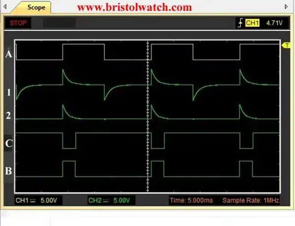
Fig. 4 Oscilloscope connections A, TP1,TP2, B, and C.
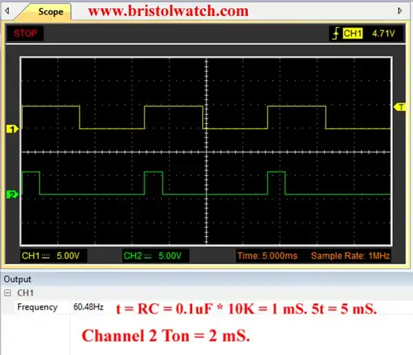
Fig. 5 Output at B with 0.10uF capacitor at 60Hz.
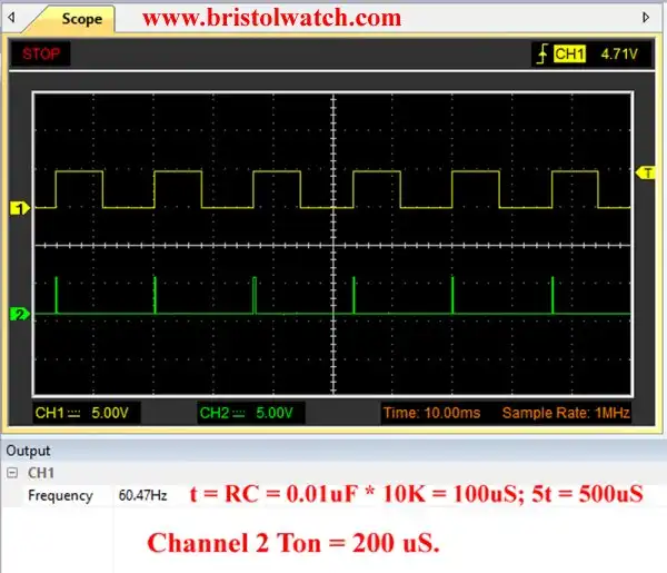
Fig. 6 Output at B with 0.01uF capacitor at 60Hz.
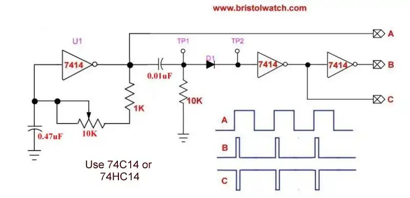
Fig. 7 SN74LS14 based square wave generator with differentiator circuit.
Fig. 7 uses the exact same circuit with a SN74LS14 square wave oscillator. The other outputs are the same.
- Quick navigation of this website:
- Basic Electronics Learning and Projects
- Basic Solid State Component Projects
- Arduino Microcontroller Projects
- Raspberry Pi Electronics, Programming
- Digital Circuits:
- Simple Schmitt Trigger SN74HC14 Square Wave Generator
- Introduction to RC Differentiator Circuits and Uses
- SN74HC14 Square Wave Generator uses SN7476 JK Flip-Flop
- SN74C14 Three Output Pulse Generator Circuit
- Astable CD4047 Geiger Counter Power Supply
- CD4047 Monostable Multivibrator Circuit
- Basic TTL Tri-State Buffer Circuit Examples
- Tutorial NOR Gate SR Latch Circuits
- Tutorial NAND Gate SR Latch Circuit
- Tutorial OR-NOR Circuits Including Monostable Multivibrator
- Brief Tutorial of XOR and XNOR Logic Gates
- LM555-NE555 One-Shot Multivibrator AC Power Control
- YouTube:
- Three Output Digital Pulse Generator
- Digital Circuits:
- Two Transistor LED Flasher Circuit
- Astable CD4047 Geiger Counter Power Supply
- CD4047 Monostable Multivibrator Circuit
- Basic TTL Tri-State Buffer Circuit Examples
- Tutorial NOR Gate SR Latch Circuits
- Tutorial NAND Gate SR Latch Circuit
- Coils for Highly Selective Crystal Radio
- Neon (NE-2) Circuits You Can Build
- Understanding Xenon Flashtubes and Circuits
Web site Copyright Lewis Loflin, All rights reserved.
If using this material on another site, please provide a link back to my site.