Solar Panel Battery Charge Controller Using Arduino
by Lewis Loflin
Follow @Lewis90068157
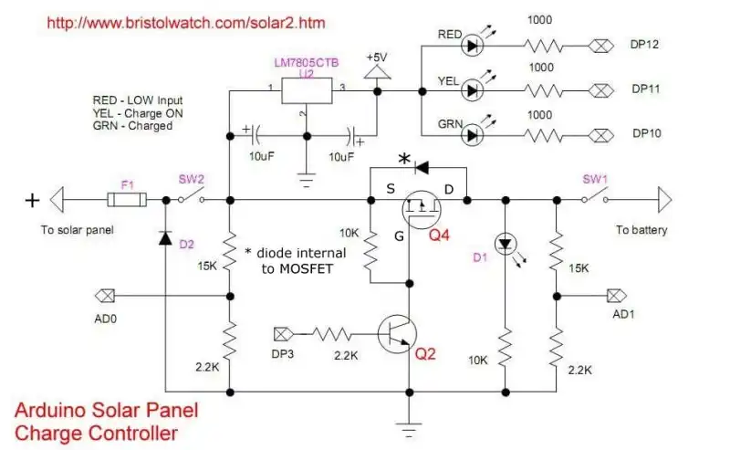
Above: Fig. 1 Schematic of solar panel charge controller using Arduino and a P-channel MOSFET.
This circuit is obsolete and for information purposes only.
- Battery Charger related:
- Arduino Solar Panel Battery Charge Controller Switching Circuit
- TL431A Lithium-Ion Cell Charging Circuits
- Charging Multi-Cell Lithium-Ion Battery Packs
- TL431 Battery Charger Voltage Detector Circuits Schematics
- TL431 Battery Charger Voltage Detector Circuits Schematics
Video: Arduino Battery Charger uses CCS and TL431 Comparators
Updated version see Solar Panel Battery Charge Controller Switching Circuit
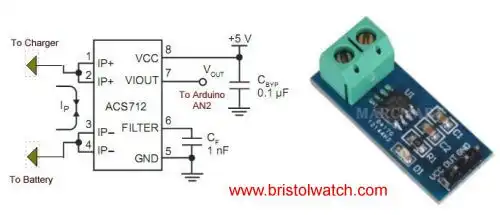
Fig. 2 ACS712 Hall effect current sensor connected to Arduino AD2.
- Solar Panel Battery Charge Controller Using Arduino
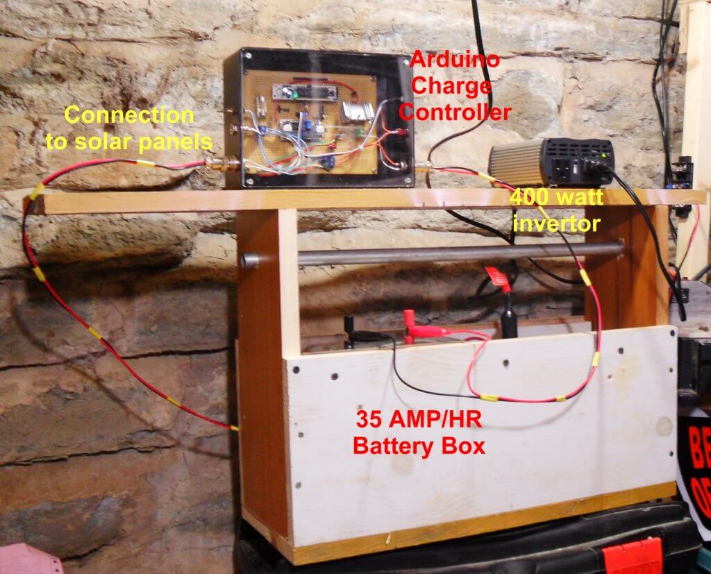
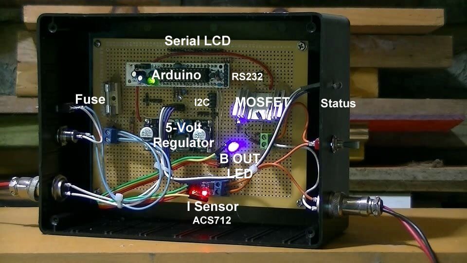
- Pictures of Power box and Arduino solar charge regulator:
- Charge Regulator with Power Box
- Connections to Regulator
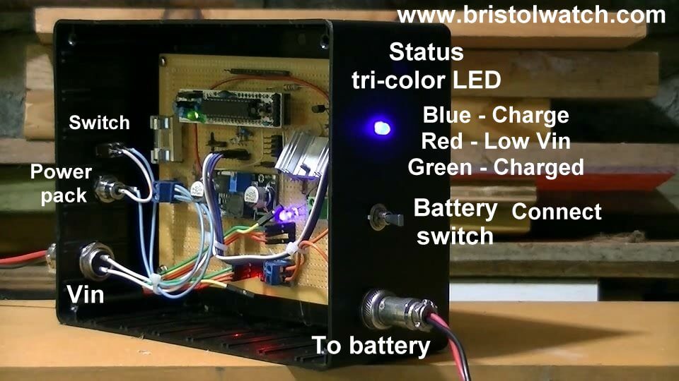
- Inside the Box
The output voltage of the ACS712 is 2.5V with no input while the spec sheet specifies 66 to 185 mV/A output sensitivity. That's a broad range and given the errors of Arduino's 10-bit ADC this gives approximate current output. Good enough for most applications.
The LED1 indicator 'bad' meaning the input voltage below the charging voltage when on.
DP3 turns on charge switch MOSFET transistor. Can use PWM or a simple timing routine. Will blink on/off with charge cycle. (Charge enable). The LED in the new circuit is merely an indicator.
LED2 indicator fully charged battery. (DP10)
A 10-bit analog-to-digital converter (ADC) has a step voltage of about 4.9 mV over a 5-volt range. This relates to the charge point (CP) variable.
To measure input voltage from the solar panel and the voltage on the battery we use a voltage divider to drop the voltage below 5-volts.
This uses 10 volt Zener diode resister combination producing 0-5 volts. The CP variable works around 600. Experiment with this.
Note the 4.9 mV was derived from the 10-bit ADC which equals 1023: 5V / 1023 = 4.9mV
Note line "chon = CP - y * 100" when uncommented the charge 'on' time will decrease gradually as battery is more charged. When fully charged the charge voltage is disabled.
Otherwise that part can be commented out and use a simple ON-OFF timing loop.
The variables chon (charge on time) and choff (charge off time) can be preset to any value.
One can experiment with this CP value. Too small, battery won't fully charge. Too large, battery will over charge. The formula is (Vin / 17,200) * 2200 / .0049.
The voltage input is connected to AD0 while the voltage on the battery is monitored at AD1. By experimentation I found a value of 600 worked well. The Zener diode setup works well.
The power for the Arduino itself can be obtained from the battery bank under charge through a 5-volt regulator. Note if the input voltage and battery is completely dead the circuit won't function with no power to Arduino.
A separate power source for the Arduino can be used. In this case a 13.5 external power supply will work for an input voltage to charge small batteries.
DP3 has pulse-width modulation built in and can be used to limit charge current (lower duty cycle) or even charging lower voltage batteries. CP or charge point will have to be changed. If one is unfamiliar with transistor switching circuits see the following:
Download the Arduino code solar1.txt.
- Comparator Circuits:
- Comparator Theory Circuits Tutorial
- Comparator Hysteresis and Schmitt Triggers
- Voltage Comparator Information And Circuits
- Looking at Window Comparator Circuits
- Analog Battery Charger Uses Comparators
- Battery Charger related:
- Solar Panel Charge Controller Using Arduino Microcontroller
- Solar Panel Charge Controller Using PICAXE Microcontroller
- Solar Panel Battery Charge Controller Using Arduino
- Solar Panel Battery Charge Controller Switching Circuit
- Solar Battery Charger videos:
- Solar Panel Battery Charge Controller Operation
- Solar Panel Battery Charge Controller Circuitry
- Solar Panel Battery Charge Controller Programming
- Tutorial Arduino Measure Current with ACS712 Hall Sensor
- Videos:
- My YouTube Videos on Electronics
- Introduction to the Arduino Microcontroller
- Part 1: Programming Arduino Output
- Part 2: Programming Arduino Input
- Part 3: Arduino Analog to Digital Conversion
- Part 4: Using Arduino Pulse-Width-Modulation
- Zero-Crossing Detectors Circuits and Applications
- Zero-Crossing Circuits for AC Power Control
- In Depth Look at AC Power Control with Arduino
- Micro-controller AC Power Control Using Interrupts
- YouTube Video for Arduino AC Power Control
- Photo Detector Devices:
- LM334 CCS Circuits with Thermistors, Photocells
- Photodiode Circuits Operation and Uses
- Photodiode Op-Amp Circuits Tutorial
- Photo Voltaic Tutorial MOSFET Output Solid State Relays
- YouTube:
- Photodiodes and How they Work
- Photodiode Op-Amp Circuits
- Using Photovoltaic MOSFET Drivers
Web site Copyright Lewis Loflin, All rights reserved.
If using this material on another site, please provide a link back to my site.