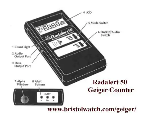
Fig. 1 Internal view Radalert50TM Geiger Counter
Astable CD4047 High Voltage Power Supply
by Lewis Loflin
YouTube video CD4047 HV Power Supply
Here I'll discuss power supplies for Geiger-Mueller tubes anyone can build. These require a high voltage but low current supply. Fig. 1 show the internal PC board of my Radalert50TM Geiger counter.
Our focus here is the power supply for the Geiger-Mueller tube in the upper right corner. This consists of some type of oscillator driving a small step up transformer, a string of diodes and capacitors forming a voltage multiplier, and a series of Zener diodes that act as a voltage regulator.
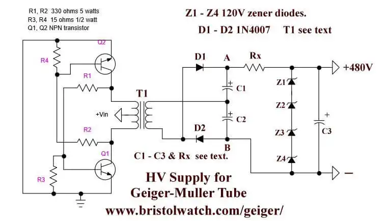
Fig. 2 Transistor-transformer oscillator circuit produces 480 volts.
The first problem is the switching transformer - those are not easily found and those offered on Ebay are expensive $30 on average. Fig. 2 uses a common small power transformer used with a transistor oscillator circuit. For more on that circuit see Simple 12 Volt DC to 120 Volt AC Inverter.
I've used this circuit to drive a 4-foot fluorescent tube with even a ballast. It produces a lot of power and the high frequency readily ionizes the gas within the tube.
Using a 12.6-volt center taped transformer for T1 at 12-13 volts produces an output of over 270 volts at several thousand Hertz - this uses what is normally the output as the input thus acting as a step up transformer. The frequency depends on the physical construction of the transformer itself.
We don't need that kind of power and that circuit is power hungry. Suppose T1 produces 250 volts out, when filtered and rectified produces 250V =~ 250 DC. volts. This is not enough to operate most Geiger-Mueller tube I know of.
C1, C2, D1, and D2 form a voltage doubler circuit producing an output of 620 volts between points A and B. Most Geiger-Mueller tubes are rated at 400-500 volts and this voltage could damage the tube.
The voltage is regulated down to 480 volts with four, 120 volt Zener diodes is series. Resistor Rx is rated at 220K to 470K at 1 watt. Because of the high frequency of the output voltage and the low current C1, C2, and C3 can be 1uF or lower. The voltage rating should be 600V.
The LND712 Geiger-Mueller tube used in the Radalert50TM is rated at 450-650 volts. The load resistor is 10 mega ohms.
Note when these circuits were built and tested an AC voltage check will be the same as the DC output once filtered and rectified. This is not the same as 60Hz. where we would multiply RMS * 1.41 to get peak.
Radalert
At these frequencies we are reading DC peak with the AC side measurement. DVMs are calibrated for 60Hz and are likely not as accurate at 1000 Hz.
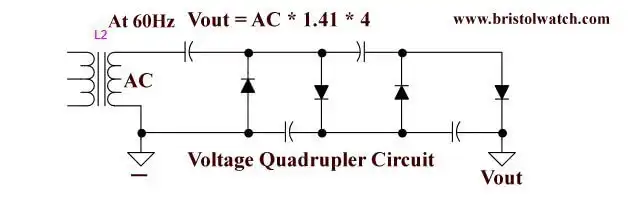
Fig. 3 Quadrupler voltage multiplier circuit.
What if the T1 output was 120 volts? Remember these capacitors charge to peak which 110 * 1.41 = 151 volts - a voltage doubler won't produce 400-500 volts. Then we do what the Radalart50TM did with a voltage quadrupler - 155 * 4 = 620 volts. Then we can use the Zeners and Rx to get a fairly regulated voltage.
That gives us flexibility on transformers, but what to with the transistors? A much better is the CD4047 astable/monostable multivibrator.
Note that the capacitors don't need to be polarized. In the case of Fig. 5 can be 0.5uF at 200 volts.
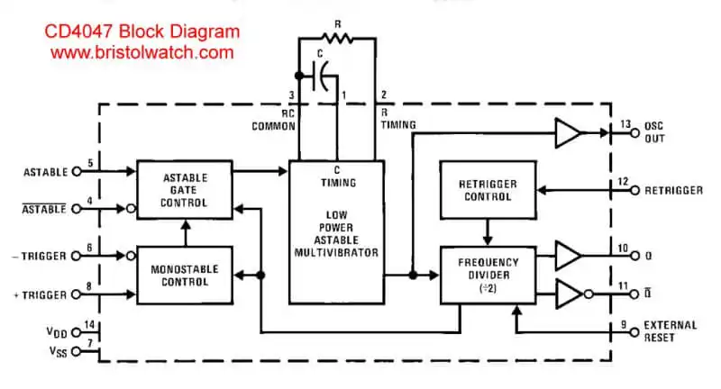
Fig. 4 CD4047 internal block diagram.
Fig. 4 shows the internal block diagram of the CD4047. This part is inexpensive, mine costs 40 cents each. It has a voltage rating of 3-15 volts and the output frequency is determined by a single capacitor and resistor.
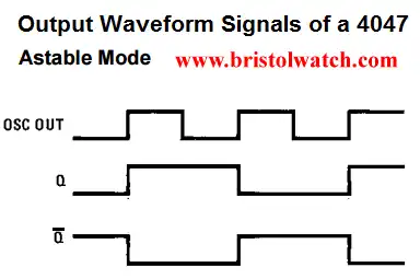
Astable mode CD4047 output waveforms.
For this application pins 10 and 11 produce a 50% duty cycle square wave - Q and QNOT are 180 degrees out of phase. In the astable mode the period (P) out = 4.40 * C * R. For example if c = 1uF and R = 10,000; P = 0.000001 * 10,000 * 4.40 = 44mSec. Frequency = 1/0.044 = 22.73 Hz.
By adjusting R one can vary the output voltage.
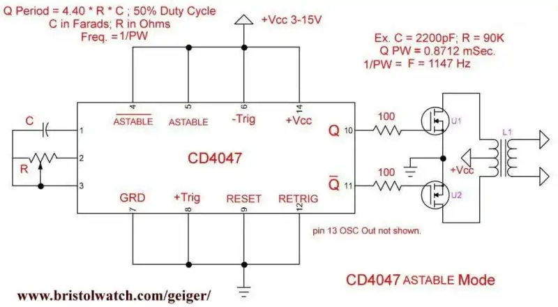
Fig. 5 CD4047 Astable Multivibrator mode with 2 power MOSFETs driving power transformer.
Fig. 5 we have replaced the bipolar transistor oscillator with the CD4047 driving two N-channel MOSFETs. Using the values list the output frequency calculates out to 1147 Hz, when I built the circuit my frequency counter read 1160 Hz.
So use the CD4027 circuit with T1, then whatever voltage multiplier circuit, then the Rx-Zener voltage regulator circuit. Be sure to read the voltage requirements of your particular Geiger-Mueller tube.
The one I bought is rated 400-500 volts. See Introduction to Geiger-Mueller Counters and Electronics
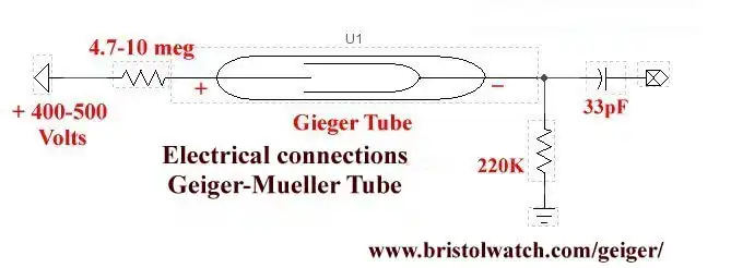
Fig. 6 Basic electrical connections Geiger-Mueller tube.
Above is the basic electrical connections for a Geiger-Mueller tube. The output goes to any number of circuits to produce an audio click or with some signal shaping to an Arduino or other microcontroller to count the pulses, etc. That will be covered on a separate page.
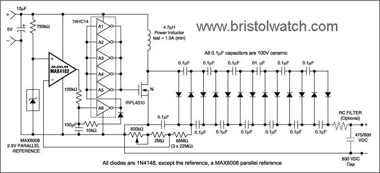
Maxim MAX4162 Geiger counter power supply uses voltage multiplier.
Finally I present a Maxim Semiconductor MAX4162 designed just for producing Geiger counter voltage without a power transformer. It's a switching type power supply using a MOSFET N and the voltage generated by a 4.7uH inductor.
It then uses a voltage multiplier circuit and utilizes feedback to regulate output voltage. I've seen similar circuits using a NE555, etc. See Bias Supply Powers Low-Power Geiger-Mueller Tube. (PDF)
- Why we should not fear nuclear power.
- Nuclear Graveyards Abound with Life
- What About Humans and Nuclear Radiation?
- Radiation Basics They Should Teach in High School
- Astable CD4047 High Voltage Power Supply
- Geiger Counter and Radioactivity
- Introduction to Geiger-Mueller Counters and Electronics
- CD4047 Monostable Multivibrator Circuit
- Getting Real About Radiation Myths and Hazards
- Uranium Hype-Facts and Virginia Uranium
- Uranium Basics and Isotopes
- Climate Change and Volcanoes
- Geiger Counter Adventures in Radioactivity Literature
- Using TL431A Li-Ion Battery Charger Tutorials
- TL431A Lithium-Ion Cell Charging Circuits
- Charging Multi-Cell Lithium-Ion Battery Packs
- TL431 Over-Voltage, Under-Voltage Detector Circuits
- TL431A Constant Current Source Working Circuits Demo
- Arduino Measures Current from Constant Current Source
- Constant Current Source Theory Testing
- Arduino Controlled Power Constant Current Source
- LM317 Adjustable Current Boost Power Supply
- Constant Current Circuits LM334, LM317
- Build LM317 0-34 Volt Power Supply
- LM334 Constant Current Source with Resistive Sensors
- LM317 High Power Constant Current Source Circuit
- LM317 Constant Current Source Circuits
- Test SCRs and Triacs
- Basic MOSFET Transistor Test Circuits
- High Voltage MOSFET Switching Circuits
- 3 Amp LM741 Op-Amp Constant Current Source
- Current Limiter Testing of Zener Diodes
- Current Limiter for Opto-Coupler Inputs
- LM317 CCS for Light Emitting Diodes
Web site Copyright Lewis Loflin, All rights reserved.
If using this material on another site, please provide a link back to my site.