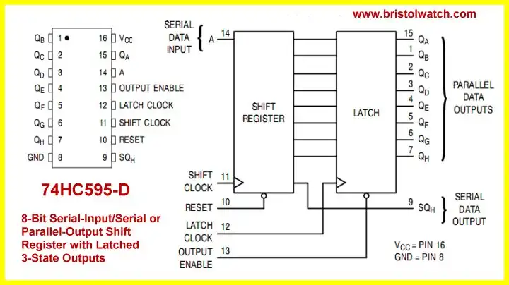
Fig. 1
Interfacing Raspberry Pi 74HC595 Serial Shift Register
See the Youtube video Raspberry Pi and the 74HC595 Serial Shift Register.
Here we look into connecting a 74HC595 8-bit serial shift register with 8-bit latch to a Raspberry Pi. Fig. 1 shows the internal configuration.
# MSB out first!
def ssrWrite(value):
    for  x in range(0,8):
        temp = value & 0x80
        if temp == 0x80:
           GPIO.output(dataBit, 1) # data bit HIGH
        else:
           GPIO.output(dataBit, 0) # data bit LOW
        pulseCLK()
        value = value <<  0x01 # shift left
    serLatch() # output byte
    return
Above is our serial shift subroutine ssrWrite(). It's nothing more than a for loop, a bitwise AND, and left-shift that sets or clears the dataBit pin, pulses HIGH then LOW the shift clock (pulseCLK), then after doing that 8 times pulses HIGH then LOW (serLatch) the latch pin. Here we shift out the most significant bit first.
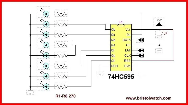
Fig. 2
Fig. 2 shows the LED connections. The LED pattern is simply a reproduction of the binary pattern shifted into the 8-bit register.
while 1:
    temp = 1
    for j in range(0, 8 ):
        ssrWrite(temp)
        temp = temp << 1
        time.sleep(.2)

    for j in range(0, 8 ):
        temp = temp >> 1
        ssrWrite(temp)
        time.sleep(.2)
The main program turns on a single LED and moves it back and forth using left and right shift commands. This consists of an infinite while loop and two for loops.
Make sure you are in the proper mode for the GPIO!
To quote,
If you use pin numbers, you don’t have to bother about revision checking, as RPi.GPIO takes care of that for you. You still need to be aware of which pins you can and can’t use though, since some are power and GND.
If you use GPIO numbers, your scripts will make better sense if you use a Gertboard, which also uses GPIO numbering. If you want to use the P5 header for GPIO28-31, you have to use GPIO numbering. If you want to control the LED on a Pi camera board (GPIO5) you also have to use GPIO numbering.
In your code add the following, but use only 1!
import RPi.GPIO as GPIO


# for GPIO numbering, choose BCM
GPIO.setmode(GPIO.BCM)


# or, for pin numbering, choose BOARD
GPIO.setmode(GPIO.BOARD)
The program code is rpi_cylon.txt.
- Quick navigation of this website:
- Basic Electronics Learning and Projects
- Basic Solid State Component Projects
- Arduino Microcontroller Projects
- Raspberry Pi Electronics, Programming
- Electronics hacks:
- Connecting PCF8574P GPIO Expander to Raspberry Pi
- Programming PCF8574P 8-bit I-O Expander with Arduino
- Raspberry Pi MM5451 LED Display Driver
- Raspberry RTC with MAX7219 Display Driver
- Raspberry Pi 8-Digit LED MAX7219 Display Driver
- Raspberry Pi 74HC595 Serial Shift Register
- Interface I2C LCD to Raspberry Pi in C
- ADS1115 4-Channel ADC Uses I2C with Raspberry Pi
- MCP4725 12-Bit DAC Interface to Raspberry Pi
- WiringPi and Pulse-Width-Modulation with Raspberry Pi
- WiringPi for Raspberry Pi and MAX6675 thermal-couple sensor
- WiringPi Blink an LED Demo
- Simple GPIO Reference Box
- Raspberry Pi with PCF8591 Analog To Digital Control in C
- Raspberry Pi PCF8591 AD-DA Sensor Python Interface
- Digital Circuits:
- Simple Schmitt Trigger SN74HC14 Square Wave Generator
- Introduction to RC Differentiator Circuits and Uses
- SN74HC14 Square Wave Generator uses SN7476 JK Flip-Flop
- Three Output Pulse Generator Circuit
- Arduino
- Arduino PWM to Analog Conversion
- Arduino Analog Digital Conversion Voltmeter
- Better Arduino Rotary Encoder Sensor
- Simple 3-Wire MAX6675 Thermocouple ADC Arduino Interface
Web site Copyright Lewis Loflin, All rights reserved.
If using this material on another site, please provide a link back to my site.