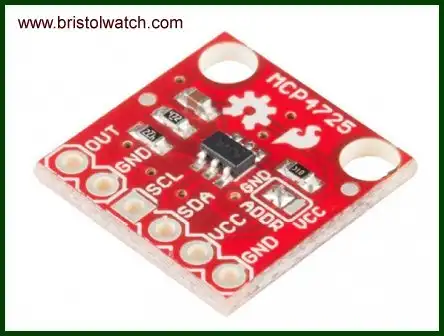
Fig. 1 MCP4725 breakout board.
MCP4725 12-Bit DAC Interface to Raspberry Pi
by Lewis Loflin
Follow @Lewis90068157
YouTube video see MCP4725 12-Bit DAC Interface to Raspberry Pi.
The MCP4725 is a 12-Bit Digital-to-Analog Converter with EEPROM Memory. Here I'll connect the MCP4725 to Raspberry Pi and illustrate how to program the device. I'll be Debian based Raspbian Linux.
Fig. 1 MCP4725 breakout board available from a number of vendors. The boards usually have pull up resistors that need to be disconnected or use a level translator which is what I did. The Raspberry Pi I2C buss is 3.3V while I operated mine at 5V.
The features of the MCP4725:
The MCP4725 is a low-power, high accuracy, single channel, 12-bit buffered voltage output Digital-to-Analog Converter (DAC) with non-volatile memory (EEPROM).
Its on-board precision output amplifier allows it to achieve rail-to-rail analog output swing. The DAC input and configuration data can be programmed to the non-volatile memory (EEPROM) by the user using I2C interface command.
The non-volatile memory feature enables the DAC device to hold the DAC input code during power-off time, and the DAC output is available immediately after power-up. This feature is very useful when the DAC device is used as a supporting device for other devices in the network.
The device includes a Power-On-Reset (POR) circuit to ensure reliable power-up and an on-board charge pump for the EEPROM programming voltage. The DAC reference is driven from VDD directly. In power-down mode, the output amplifier can be configured to present a low, medium, or high resistance output load.
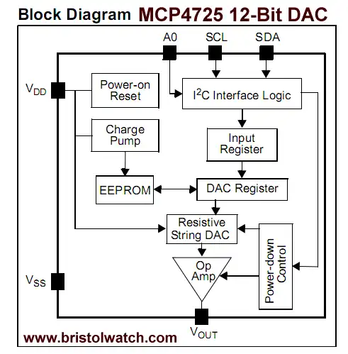
Fig 2 MCP4725 internal block diagram.
Looking Closer
The MCP4725 DAC is a 12-bit device with values from 0-4095, with 4095 outputting a voltage near Vcc. First we write a control byte with the following specifications:
(Refer to page 18-19 spec sheet), uint8_t control_byte = 0b01000000; bits 7-5 are 010 write DAC only, 011 write DAC and EEPROM. We can write the 12-bit value to the DAC only or the DAC and the EEPROM. The values stored in the EEPROM sets the power up output voltage. This is byte 0.
If say 2048 is stored in the EEPROM the voltage output when power up is 1/2 Vcc.
The uint8_t is an unsigned 8-bit integer value that's defined across multiple versions of C.
In the example here I write to the DAC only because there's a delay writing to the EEPROM, in addition so many write cycles will shorten the life of the EEPROM.
Bits 4-3 are unused while bits 2-1 setup power down (PD) where a selected resistor value is switched from the output to ground. I set this value to open. Bit 0 is also unused.
The next two bytes are also uint8_t variables. The uint16_t val is an unsigned 16-bit integer value where one enters a value from 0-4095. The variable val is shifted four places right and loaded into byte 1 as the 8 MSB of val.
Then val is shifted four places left and loaded into byte 2 where bits 7-4 are the LSB if val while bits 3-0 are unused.
Then all three bytes are sent over I2C to the MCP4725 that outputs a voltage based on the value of val. After the three bytes are written the program exits.
Full program mcp4725.txt.
// Lewis Loflin lewis@bvu.net
// http://www.bristolwatch.com/rpi/mcp4725.html
// MCP4725.c
// Program the MCP4725 DAC
#include <stdio.h>
#include <sys/types.h>
#include <sys/stat.h>
#include <fcntl.h>
#include <unistd.h>    // read/write usleep
#include <stdlib.h>    // exit function
#include <inttypes.h>  // uint8_t, etc
#include <linux/i2c-dev.h> // I2C bus definitions

int fd;
int mcp4725_address = 0x62;
int16_t val;
uint8_t writeBuf[3];
float myfloat;

int main()   {

  // open device on /dev/i2c-1 the default on Raspberry Pi B
  if ((fd = open("/dev/i2c-1", O_RDWR)) < 0) {
    printf("Error: Couldn't open device! %d\n", fd);
    exit (1);
  }

  // connect to ads1115 as i2c slave
  if (ioctl(fd, I2C_SLAVE, mcp4725_address) < 0) {
    printf("Error: Couldn't find device on address!\n");
    exit (1);
  }

  // 12-bit device values from 0-4095

  // page 18-19 spec sheet
  writeBuf[0] = 0b01000000; // control byte
  // bits 7-5; 010 write DAC; 011 write DAC and EEPROM
  // bits 4-3 unused
  // bits 2-1 PD1, PD0 PWR down P19 00 normal.
  // bit 0 unused

  writeBuf[1] = 0b00000000; // HIGH data
  // bits 7-0 D11-D4


  writeBuf[2] = 0b00000000; // LOW data
  // bits 7-4 D3-D0
  // bits 3-0 unused

  // input number from 0-4095
  // 2048 50% Vcc
  char buffer [15];
  printf ("Enter a number 0-4095: ");
  scanf("%s", buffer);
  // string to int
  val = atoi(buffer);
  printf("You entered %d  ", val);

  // write number to MCP4725 DAC
  writeBuf[1] = val >> 4; // MSB 11-4 shift right 4 places
  printf("WriteBuf[1] = %d  ", writeBuf[1]);

  writeBuf[2] = val << 4; // LSB 3-0 shift left 4 places
  printf("WriteBuf[2] = %d  \n", writeBuf[2]);

  if (write(fd, writeBuf, 3) != 3) {
    perror("Write to register 1");
    exit (1);
  }

  close(fd);
  return 0;

}
- Software and setup:
- Raspberry Pi Openbox Desktop 2019
- Setting up Openbox for Raspberry Pi
- Add Solid State Hard Drive to Raspberry Pi
These are mostly sensors connected through the I2C protocol. While digital themselves, they can measure analog sensors.
- Interface I2C LCD to Raspberry Pi in C
- ADS1115 4-Channel ADC Uses I2C with Raspberry Pi
- MCP4725 12-Bit DAC Interface to Raspberry Pi
- Raspberry Pi with PCF8591 Analog To Digital Control in C
- Raspberry Pi PCF8591 AD-DA Sensor Python Interface
- Using the powerful Rox-Filer system in Linux
- Use FEH under Linux for a Wallpaper Setter
- How to create Symbolic links in Linux
- Raspberry Pi USB Audio Connection
- WiringPi for Raspberry Pi and MAX6675 thermal-couple sensor
- WiringPi Blink an LED Demo
- WiringPi and Pulse-Width-Modulation with Raspberry Pi
- Raspberry Pi and a MM5451 LED Display Driver
- Raspberry Pi MM5451 LED Display Driver YouTube
- Raspberry Pi RTC with MAX7219 Display Driver
- Raspberry Pi Python RTC with MAX7219 Display Driver YouTube
- Raspberry Pi 8-Digit LED MAX7219 Display Driver
- Raspberry Pi and the 74HC595 Serial Shift Register
- Programming Raspberry Pi 74HC595 Serial Shift Register YouTube
- Raspberry Pi and Arduino
- Connect Serial LCD to Raspberry Pi
- Serial Read from Arduino to Raspberry Pi
- Arduino Raspberry Pi Interface with LCD Display
- Connecting Raspberry Pi to Arduino with I2C Interface
- Connecting Raspberry Pi to Arduino with I2C Interface
Web site Copyright Lewis Loflin, All rights reserved.
If using this material on another site, please provide a link back to my site.