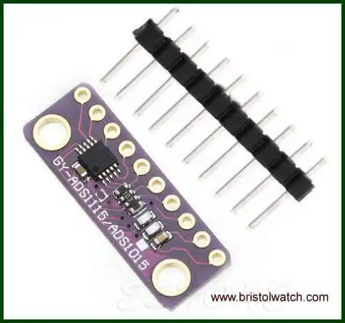
Fig. 1 ADS1115 PC board assembly.
ADS1115 4-Channel ADC Uses I2C with Raspberry Pi
by Lewis Loflin
Follow @Lewis90068157
The ADS1115 is a 4-channel analog-to-digital converter utilizes the I2C proto call with selectable addresses. Here we look at connecting this device with the Raspberry Pi running the Debian based Raspbian operating system. The reality is we are using a Linux system.
YouTube video: ADS1115 4-Channel ADC Uses I2C with Raspberry Pi.
Fig. 1 illustrates a breakout board and the ultra small integrated circuit. While mine was purchased off Ebay, but is also available from Sparkfun.com and Adafruit.com. Most material on the web concerns connections to Arduino with annoying pre-made libraries that disclosed nothing on the actual programming.
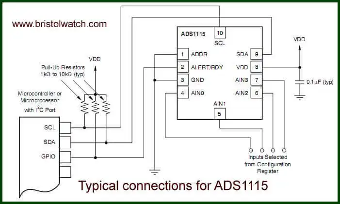
Fig. 2 Electrical connections ADS1115.
Fig. 2 illustrates the typical ADS1115 electrical connections.
Like my other projects I present direct program code examples tested and working. There program uses the TMP37 analog Centigrade temperature sensor on AIN0. For more on the TMP37 electrical connections see:
Also ads1115.pdf spec sheet.
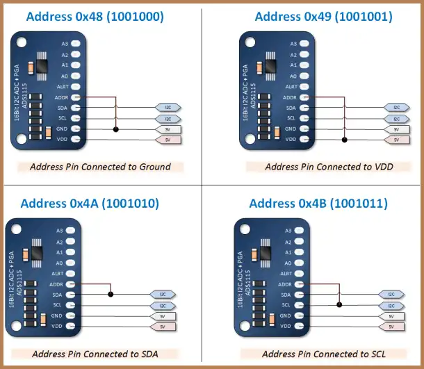
Fig. 3 ASD1115 addressing connections.
Fig. 3 shows the addressing scheme for the ADS1115 - the breakout boards have a pin ADDR and connect as shown above for a particular address I used 0x48.
An issue to be aware of is the pull up resistors built into the boards as shown in Fig. 2. The Raspberry Pi I2C connections is 3.3-volts and has its own pull up resistors. This may create problems - either remove/cut the pull ups or in my case I used a level translator to operate the ADS1115 at 5-volts and isolate the pull up problem.
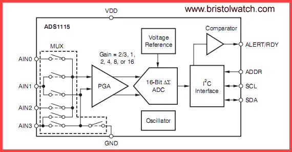
Fig. 4 ADS1115 internal block diagram.
Fig. 4 shows the internal block diagram of the ADS1115 ADC with 16-bit resolution.
Bits D14-D12 are used for input select. For a closer look at MUX switching see ads1115_mux.jpg. Let's take a closer look at the internal registers within the ADS1115.
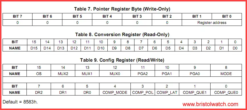
Fig. 5 internal ASD1115 registers.
Click for larger image.
Fig. 5 shows three registers in the ADS1115. The first is a 8-bit "pointer" register that directs data to either the 16-bit read-only conversion register (0) or the 16-bit read/write config register (1). While the program below goes into all the config register bits I'll cover the most important parts of the config register.
Bits D11-D9 Amplifier gain (partial):
000 : FS = +-6.144V(1)
001 : FS = +-4.096V(1)
010 : FS = +-2.048V (default)
011 : FS = +-1.024V
Bits D11-D9 determine the internal amp gain - it sets the upper voltage limit of the ADCs. Because I used 5 volts I selected "001". Don't be fooled by 6.144 volts because the device operates at a max voltage of 5.5 volts. Even at 5 volts the device will never read anywhere near that level.
If one is operating the ADS1115 at 3.3 volts one must select 2.048V or "010". With a Vmax of 4.096 the voltage per step (VPS) at 15 bit (2^15) is:
VPS = 4.096 / 32768 = 125 uV per step. Arduino with a 10-bit resolution is 5 / 1023 = 4.887 mV per step. The ADS1115 has almost 40 times the resolution of Arduino.
Bit D8 Mode Select:
0 : Continuous conversion mode
1 : Power-down single-shot mode (default)
D8 is the mode select bit. A "0" activates the continuous mode where once written to one could simply read the conversion register with no further writes to the config register.
A "1" (default) in D8 is the one-shot mode. In that mode the ADS1115 does a conversion after the write then powers down to low current mode. Bit D15 serves as a ready flag and when set data is ready.
The following code snippet illustrates this. :
// wait for conversion complete
  // checking bit 15
  do {
    if (read(fd, writeBuf, 2) != 2) {
      perror("Read conversion");
      exit(-1);
    }
  }
  while ((writeBuf[0] & 0x80) == 0);
There are two program files the first demonstrates the single shot mode where it measures the value of a potentiometer connected to ANC1 and print out the voltage reading from 0-4.2 volts on the terminal.
See ads1115a.c
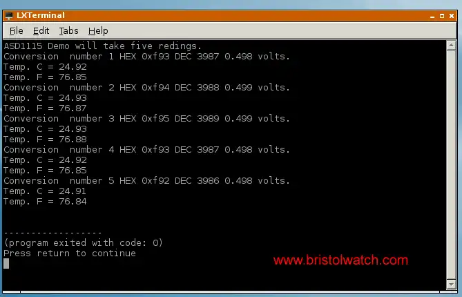
Fig. 6 terminal output of five readings of TMP37 sensor.
The second demonstrates continuous mode see ads1115c.c
- Software and setup:
- Raspberry Pi Openbox Desktop 2019
- Setting up Openbox for Raspberry Pi
- Add Solid State Hard Drive to Raspberry Pi
These are mostly sensors connected through the I2C protocol. While digital themselves, they can measure analog sensors.
- Interface I2C LCD to Raspberry Pi in C
- ADS1115 4-Channel ADC Uses I2C with Raspberry Pi
- MCP4725 12-Bit DAC Interface to Raspberry Pi
- Raspberry Pi with PCF8591 Analog To Digital Control in C
- Raspberry Pi PCF8591 AD-DA Sensor Python Interface
- Using the powerful Rox-Filer system in Linux
- Use FEH under Linux for a Wallpaper Setter
- How to create Symbolic links in Linux
- Raspberry Pi USB Audio Connection
- WiringPi for Raspberry Pi and MAX6675 thermal-couple sensor
- WiringPi Blink an LED Demo
- WiringPi and Pulse-Width-Modulation with Raspberry Pi
- Raspberry Pi and a MM5451 LED Display Driver
- Raspberry Pi MM5451 LED Display Driver YouTube
- Raspberry Pi RTC with MAX7219 Display Driver
- Raspberry Pi Python RTC with MAX7219 Display Driver YouTube
- Raspberry Pi 8-Digit LED MAX7219 Display Driver
- Raspberry Pi and the 74HC595 Serial Shift Register
- Programming Raspberry Pi 74HC595 Serial Shift Register YouTube
- Raspberry Pi and Arduino
- Connect Serial LCD to Raspberry Pi
- Serial Read from Arduino to Raspberry Pi
- Arduino Raspberry Pi Interface with LCD Display
- Connecting Raspberry Pi to Arduino with I2C Interface
- Connecting Raspberry Pi to Arduino with I2C Interface
This is a collection of programs and hardware hacks related to mainly Raspberry Pi and Debian Linux.
- Main Light Fast Linux Desktops with Openbox, JWM
- Test Reuse Surplus PC Power Supplies
- Add WBAR Launch Dock to Raspberry Pi
- Add MPG123 Terminal Music Player to Raspberry Pi, Linux
- Basics of Alsamixer Audio Control for Linux
- Add Solid State Hard Drive to Raspberry Pi
- Beep a PC Speaker Add Beeper to Raspberry Pi
- Using FEH Wallpaper Setter Under Linux
- Scrot Lite Weight Screen Shot Software for Linux
- Using Light Weight Beaver Text Editor
- Install Viewnior Image Viewer for Linux
- Zmixer ALSA Sound Control Tutorial
- Tutorial Xinitrc Desktop Manager Control for Linux
- Setup Raspberry Pi Using JWM Window Manager
Web site Copyright Lewis Loflin, All rights reserved.
If using this material on another site, please provide a link back to my site.