Using Arduino with a DS1307 Real Time Clock
by Lewis Loflin
Explanation of program:
On power up or reset the "setup" is executed once, setting up the hardware and writing the time/date to the Ds1307. Then the "loop" section will run over and over. The DS1307 is read and sent via the serial port to a computer running for example Hyper Terminal. This demonstrates the use of the Wire.h library, serial ports, and the DS1307.
For the basic structure of an Arduino program see page 7 of Arduino Programming Notebook by Brian Evans
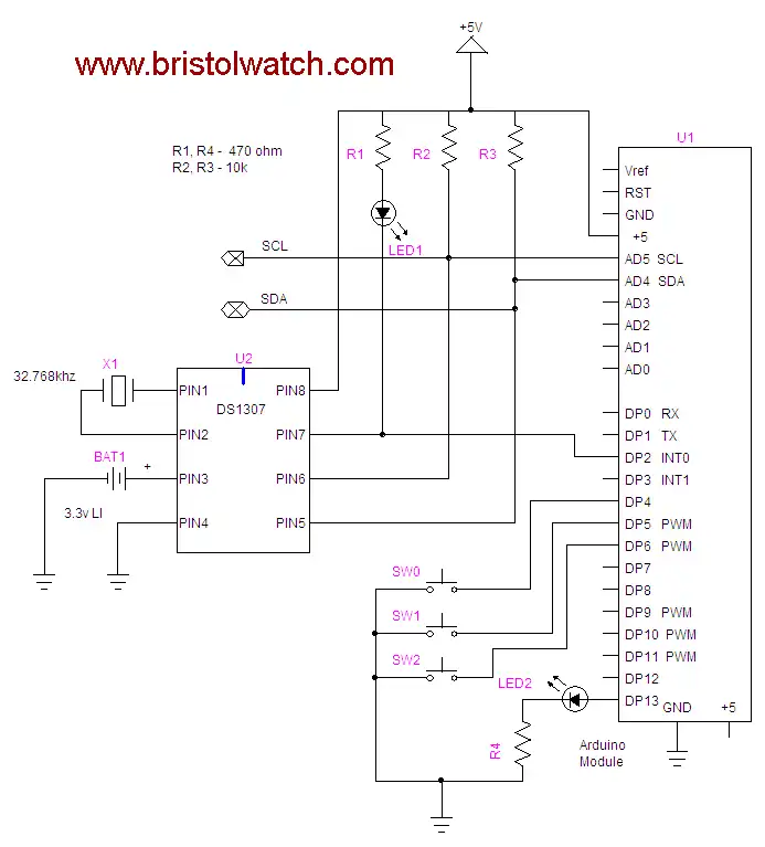
The 1 Hz output from the DS1307 has been connected to digital pin 2 in order to update the output to once a second. This can be a 10K resistor or an LED-1k resister combination to observe the output from the Ds1307.
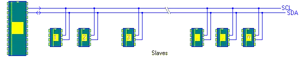
Basic I2C setup.
The DS1307 is a low-power clock/calendar with 56 bytes of battery-backed SRAM. The clock/calendar
provides seconds, minutes, hours, day, date, month, and year information. The date at the end of the
month is automatically adjusted for months with fewer than 31 days, including corrections for leap year.
The DS1307 operates as a slave device on the I2C bus. Access is obtained by implementing a START
condition and providing a device identification code (0x68) followed by a register address. Subsequent registers
can be accessed sequentially. The DS1307 comes in an 8-pin dip package. The Ds1307 counts in BCD format.
Bit 7 of Register 0 is the clock halt (CH) bit. When this bit is set to 1, the oscillator is disabled. When cleared to 0, the oscillator is enabled. In other words unless this is cleared the clock will not run!
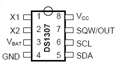
Ds1307 pin out
Only the first 8 bytes (0x00 - 0x07) are used by the clock itself while the other 56 bytes can be used a scratchpad RAM.
PIN DESCRIPTION
Pins 1, 2 Connections for Standard 32.768kHz Quartz Crystal. No capacitor or other parts needed.
Pin 3 VBAT Backup Supply Input for Any Standard 3V Lithium Cell Diodes in series between the battery and the VBAT pin may prevent proper operation!
Pin 4 GND Ground
Pin 5 SDA Serial Data Input/Output. SDA is the data input/output for the I2C serial interface. The SDA pin is open drain and requires an external pull-up resistor. Arduino pin 4.
Pin 6 SCL Serial Clock Input. SCL is the clock input for the I2C interface and is used to synchronize data movement on the serial interface. Arduino pin 5.
7 SWQ/OUT Square Wave/Output Driver. When enabled, the SQWE bit set to 1, the SQW/OUT pin outputs one of four square-wave frequencies (1Hz, 4kHz, 8kHz, 32kHz). The SQW/OUT pin is open drain and requires an external pull-up resistor. SQW/OUT operates with either VCC or VBAT applied. An LED and 220 ohm resistor in series tied to VCC will produce a 1 HZ blink. This is a good way to tell if the clock chip is working.
8 VCC (5 volts)
For more information on the DS1307 see Dallas DS1307 Real Time Clock I2C plus RAM
Arduino code for this project: arduino_ds1307.txt.
- Connecting the ATMEGA168/Arduino to MCP23016 and LCD Display
- Display Time/Date with Arduino, LCD Display, and Ds1307 RTC
Setting Hours and Minutes
Assuming the switches are wired as shown above, close SW0 and while closed SW1 and SW2 will increment the hours and minutes as shown on the terminal. Release/open SW0 and new time will be written to the DS1307.
![]()
- Quick navigation of this website:
- Basic Electronics Learning and Projects
- Basic Solid State Component Projects
- Arduino Microcontroller Projects
- Raspberry Pi Electronics, Programming
Stepper Motors
- Easy Driver Micro-Stepper Controller to Arduino
- Unipolar Stepper Motor with a Arduino
- Considerations for Using Stepper Motors
- Connecting the Arduino to a L298N H-Bridge
- L298N Motor Controller Theory and Projects
- TA8050 H-Bridge Motor Controller
- Battery Charger related:
- Solar Panel Charge Controller Using Arduino
- Solar Panel Battery Charge Controller Using Arduino
- Solar Panel Battery Charge Controller Switching Circuit
- Arduino AC Power Control Tutorial
- Rotary Encoder Using Arduino Hardware Interrupts
- Arduino Controlling 74C164 Shift Register
- Arduino Interface MC3479 Stepper Motor Controller
Serial LCD Display and assorted Sensors
- Arduino LCD Display using 74164 Shift Register
- Arduino LCD Display with DS18B20
- Arduino LCD Display with DHT11 Sensor
- Arduino with MM5451 LED Display Driver
- Arduino MAX7219 Operates 8X8 LED Matrix
- Arduino RTC Clock MAX7219 LED Display
- BCD Conversion with MAX7219
- Hatching Chicken Eggs with Arduino
- Arduino TMP37 Temperature Sensor
- Arduino TMP37 Temperature Sensor Tutorial
- Testing the Keyes IR Sensor Module with Arduino
- Arduino to MCP23016, LCD Display
- Time-Date with Arduino, LCD Display, DS1307 RTC
- Controlling Driveway Lights with the Arduino
- TSL230R Light to Frequency Converter
- Arduino with MCP23016 I/O Expander
- Arduino DS1307 Real Time Clock
- Arduino with 24LC08 Serial EEPROM
- MC3479 Stepper Motor Controller with Arduino
Web site Copyright Lewis Loflin, All rights reserved.
If using this material on another site, please provide a link back to my site.