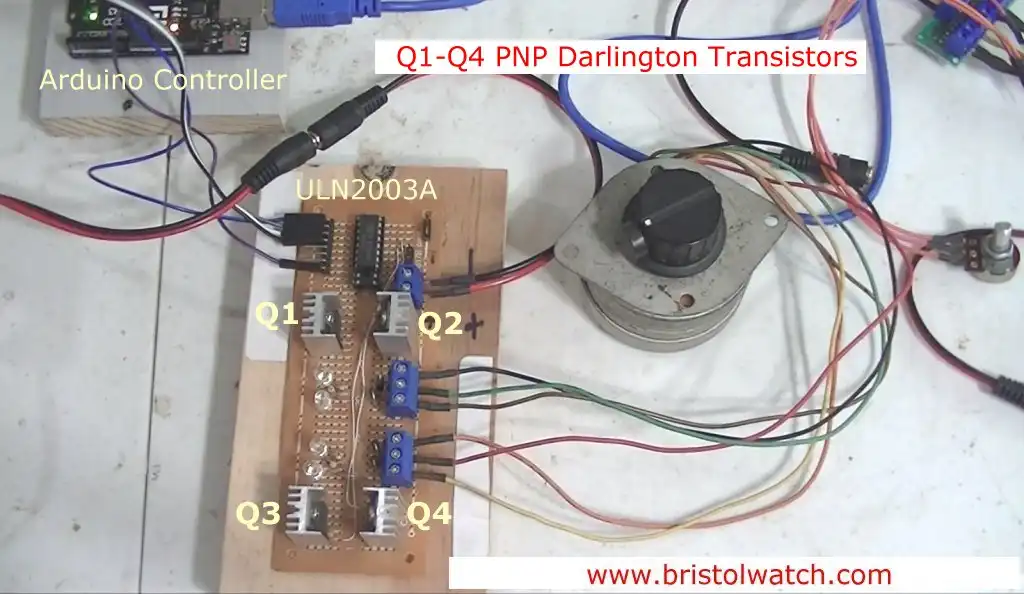
Fig. 1 Arduino with unipolar stepper driver control board.
Click for larger image.
Arduino Power Magnetic Driver Power Board
by Lewis Loflin
Follow @Lewis90068157
Note: click on any image for larger view.
This consists of two parts. The diagram of the driver board is self-explanatory. I use the open-collector ULN2003A to turn on a PNP transistor Vcc switch.
I use four TIP125 power Darlington transistors. They are rated at 5 amps at 60-volts. I use this to drive a unipolar stepper motor.
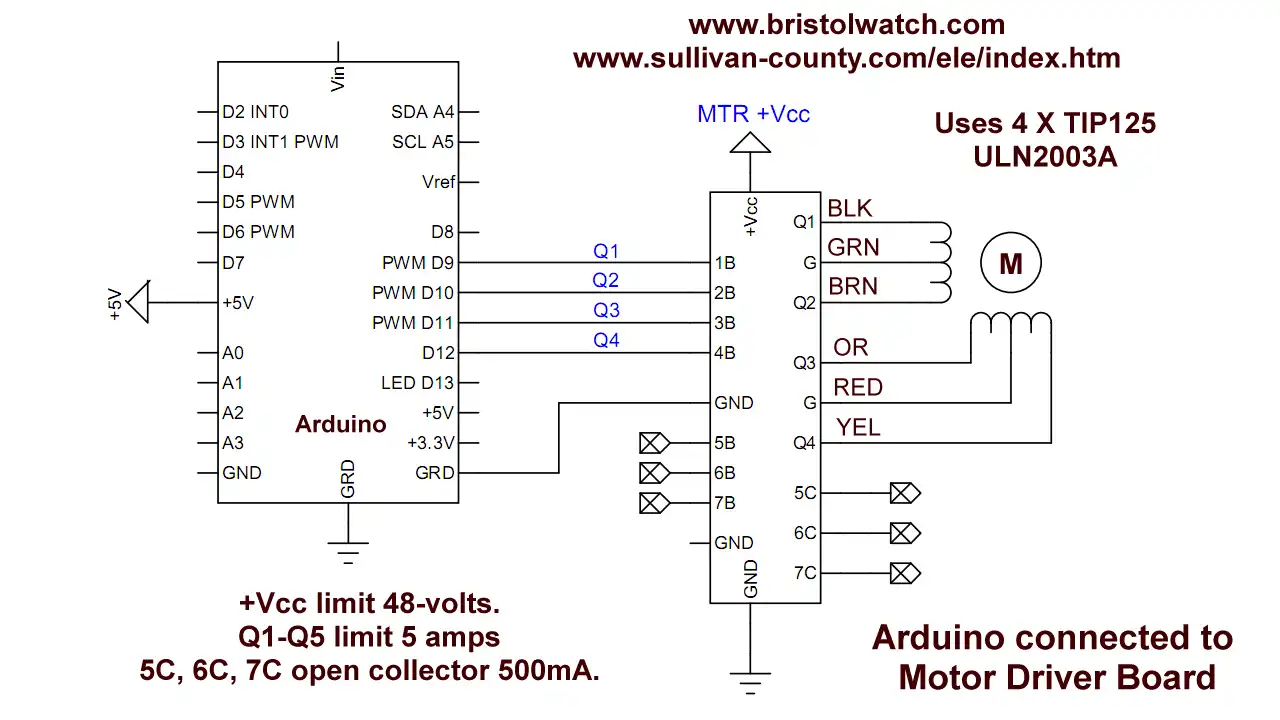
Fig. 2 Electrical connections Arduino with unipolar stepper driver control board.
Click for larger image.
Stepper motor and Arduino connections. The board has seven inputs. Four are used to drive ULN2003A inputs to drive the power transistors.
The remaining three of seven ULN2003A drivers are bought out to header pins. These are open-collector rated at 50-volts at 500mA.
Note the stepper motor connections must be connected as shown. Other motors with different colors are a matter of trial-error.
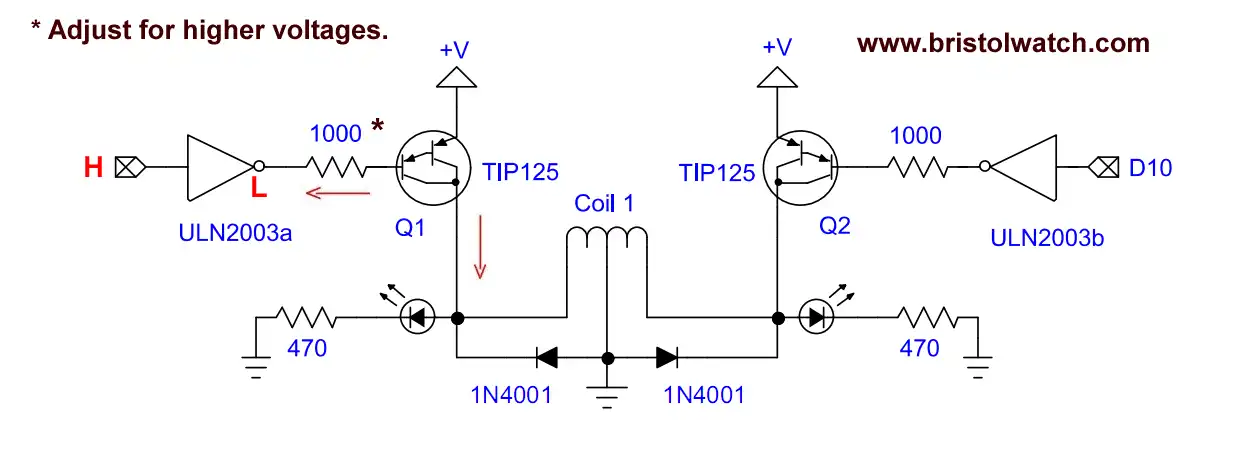
Fig. 3 TIP125 driver pair diagram for each stepper winding.
Click for larger image.
The electrical connections to each stepper motor winding uses a pair of transistors.
A HIGH input switches the ULN2003A driver to ground. The creates an emitter-base current turning the collector-emitter current to drive the load.
The TIP125 has internal suppressor diodes from collector-emitter and I added 1N4001 diodes as shown.
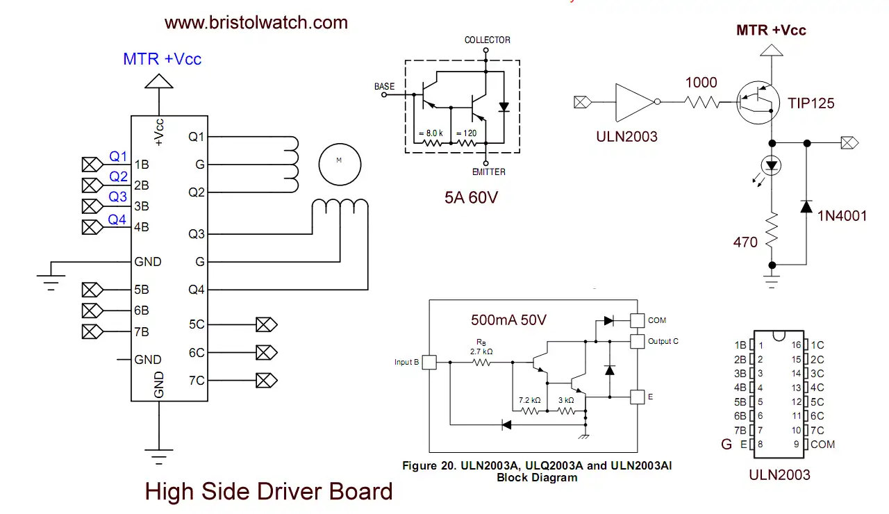
Fig. 4 various parts used in unipolar stepper motor board.
Click for larger image.
Internal parts of the driver board.
Note the motor supply voltage was passed through a constant current source set to 1 amp.
Code
The code was written originally for a 12-volt Airpax stepper motor. It consists of two subroutines forward(count, step_delay) and reverse(count, step_delay).
It consists of a sequence of 4-bit stepper out bits turning ON-OFF the various halves of each coil.
The forward or clockwise subroutine is stepped through an infinite while loop. Each step decrement a variable "count" that breaks the loop at count = 0.
Reverse or counter-clockwise is the same the sequence is reversed.
One can use direct port commands or a string of digitalWrite() commands, four per step.
See Arduino Port Registers Revisited.
The winding are switched all off before the next 4-bits are written.
The stepper motor webpage goes more into how stepper motors operate. See Using a Unipolar Stepper Motor with a Arduino.
The new code is as follows original code on the Arduino stepper motor page.
Download the Arduino code ard_stepper.txt

- Coils for Highly Selective Crystal Radio
- Neon (NE-2) Circuits You Can Build
- Understanding Xenon Flashtubes and Circuits
- Hall Effect Magnetic Switches and Sensors
- Transistor-Zener Diode Regulator Circuits
- Build an Adjustable 0-34 volt power supply with the LM317
- Simple 2 Transistor LED Flasher Circuit
- LM2575 Simple Switching Voltage Regulators
- LM317 Constant Current Source for Lighting LEDs
- IGBT Based High Voltage H-Bridge DC Motor Control
- Arduino Controlled IR2110 Based H-Bridge HV Motor Control
- Understanding Unijunction Transistors Theory Operation
- Arduino Measures Current from Constant Current Source
- Constant Current Source Theory Testing
- Review Ohm's Law for Trouble-Shooting CCS Circuits
- Arduino Power Magnetic Driver Board for Stepper Motors
- Arduino Controlled Power Constant Current Source
- Theory and Operation of Capacitors
Related video to above:
- Measure Current from Constant Current Source with Arduino
- Constant Current Source Multimeter Trouble Shooting
- Ohm's Law Review for Constant Current Source
- Arduino Unipolar Stepper Motor Driver Board with Arduino Code
- Arduino Controlled Constant Current Source
- LM317 Adjustable Current Boost Power Supply
- Constant Current Circuits LM334, LM317
- Build LM317 0-34 Volt Power Supply
- LM334 Constant Current Source with Resistive Sensors
- LM317 High Power Constant Current Source Circuit
- LM317 Constant Current Source Circuits
- Test SCRs and Triacs
- Basic MOSFET Transistor Test Circuits
- High Voltage MOSFET Switching Circuits
- 3 Amp LM741 Op-Amp Constant Current Source
- Current Limiter Testing of Zener Diodes
- Current Limiter for Opto-Coupler Inputs
- LM317 CCS for Light Emitting Diodes
Web site Copyright Lewis Loflin, All rights reserved.
If using this material on another site, please provide a link back to my site.