
Exploring the unseen: A Crookes tube reveals the elegance of natural laws.
Larger Image | Visit Hobby Page
Hello, I’m Lewis Loflin — and this is not an Arduino tutorial. This is science.
Electronics is a form of applied physics. That means real currents, real voltages, and real charge movement — not abstractions.
What you're about to see isn’t another plug-and-play tutorial. This is real electronics — grounded in testable, material science.
I treat electronics as what it is: applied physics.
I do not — and will not — teach positive current flow as a valid model. Why? Because it fails to explain:
In this series, you’ll see working physical examples: lab-built circuits, ion beam demonstrations, and working models of devices that depend on actual electron and ion movement.
If you're tired of plug-and-play fluff and want real science that explains the real world — you're in the right place.
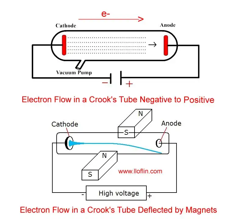
Electron flow in a Crook’s tube under high voltage.
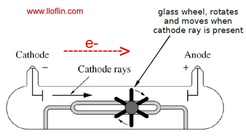
Electron flow from negative to positive in a Crook’s tube turns a pinwheel.
Conventional current is the idea that electric current flows from positive to negative.
This model dates back to the 1700s — before electrons were discovered. Scientists like Benjamin Franklin assumed charge flowed from the positive terminal. That convention stuck, even after we learned the truth.
In reality:
Electron flow matches the direction of physical charge movement — not just theory or diagram arrows.
That’s why in this series, we use electron flow only. It matches the science — and the hardware.
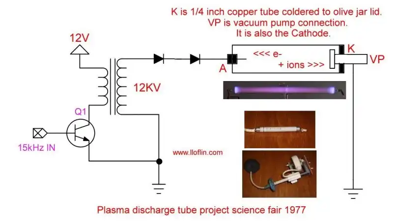
See Crookes Tube Science Fair Project (1977).
See General Science for Everyone – Cloud Chambers
Gas discharge tubes — from Crookes tubes to fluorescent lights — rely on plasma: a mixture of free electrons and positive gas ions formed in a low-pressure gas under high voltage.
Electrons move to the anode (+), and positive ions accelerate toward the cathode (−). But those ions don’t just hit and stop — they collide with real force, damaging the electrode surface.
In my Crookes tube experiment, I observed this directly — the copper target developed a visible pit from ion impact.
This isn’t theoretical. This is **measurable, physical damage** — caused by charged particles slamming into metal at high energy.
Plasma is powerful, but it comes at a cost. Every flash and glow leaves a mark.

An electrical ballast is a device placed in series with a load to limit the amount of current in an electrical circuit. A familiar and widely used example is the inductive ballast used in fluorescent lamps to limit the current through the tube, which would otherwise rise to a destructive level due to the negative differential resistance of the tube's voltage-current characteristic. Wiki
See negative resistance below.
Fluorescent lamps use a low-pressure mercury vapor arc discharge to produce ultraviolet (UV) light, which then excites a phosphor coating on the inside of the tube to emit visible light.
At low temperatures, ionization is harder due to lower atomic energy levels and fewer free electrons. More voltage is needed to start the lamp. Preheating the electrodes helps overcome this.
Once the arc is formed, plasma has very low resistance. If not limited, the current would increase rapidly and destroy the lamp. That’s why all discharge lamps require a current-limiting ballast — to stabilize operation.
A fluorescent lamp ballast serves two essential functions:
Without a ballast, the lamp would either not start — or self-destruct due to uncontrolled current. The ballast ensures both safe ignition and stable operation.
Note: Ionization of low-pressure gas is not automatic — it requires sufficient voltage to begin conduction, just like in a neon sign or Crookes tube.
In a classic preheat fluorescent circuit (choke ballast + glow-bottle starter), the small capacitor inside the starter is wired across the starter’s contacts. It acts as a snubber: reduces contact arcing and suppresses radio-frequency noise. It is not the same as the large power-factor correction capacitor sometimes found across the mains in fixtures.
This circuit operates at mains voltage. Use proper isolation, discharge capacitors before handling, and only service with appropriate skills and safety gear.
This reference compares three common selenium HV rectifiers used in CRT televisions and high-voltage circuits. These devices are low-current, high-voltage rectifiers — not to be confused with silicon power diodes.
| Part Number | Reverse Voltage (VR) | Forward Current (IF) | Application | Notes |
|---|---|---|---|---|
| NTE504 | ~23,000 V | ~0.2 mA | Flyback HV rectifier | Replaces GECR-6, low-current selenium, epoxy case |
| GECR-6 | ~23,000 V | ~0.2 mA | Same as NTE504 | Compact axial-leaded selenium stack |
| ECG118 | ~6,500 V | ~0.5 mA | Focus rectifier | Used in CRT focus bias circuits |
Reminder: These are not high-current devices. Despite the high voltage, low current (under 2mA) for CRT anodes.
| Element | Symbol | Approx. Abundance (ppm) | Common Semiconductor Use |
|---|---|---|---|
| Silicon | Si | ~282,000 | Base for most integrated circuits and solar cells |
| Germanium | Ge | ~1.5 | High-speed transistors, fiber optics, infrared detectors |
| Selenium | Se | ~0.05 | Photovoltaics, rectifiers, photocells |
| Tellurium | Te | ~0.001 | CdTe solar cells, thermoelectrics |
| Gallium | Ga | ~0.019 | GaAs, GaN semiconductors, LEDs, solar cells |
| Arsenic | As | ~1.8 | GaAs, III-V semiconductors |
| Indium | In | ~0.05 | InP semiconductors, ITO coatings, CIGS solar cells |
| Cadmium | Cd | ~0.1 | CdTe solar cells, photodetectors |
Note: ppm = parts per million by weight. These values are approximate averages and may vary by source.
| Element | Abundance (ppm) | Rarity Status |
|---|---|---|
| Silicon | ~282,000 | Very abundant |
| Arsenic | ~1.8 | Common |
| Germanium | ~1.5 | Moderately abundant |
| Indium | ~0.05 | Scarce |
| Tellurium | ~0.001 | Very rare |
✅ Conclusion: Arsenic is not rare at all, and germanium — while less abundant — is still far more available than many specialized semiconductor materials like indium and tellurium.
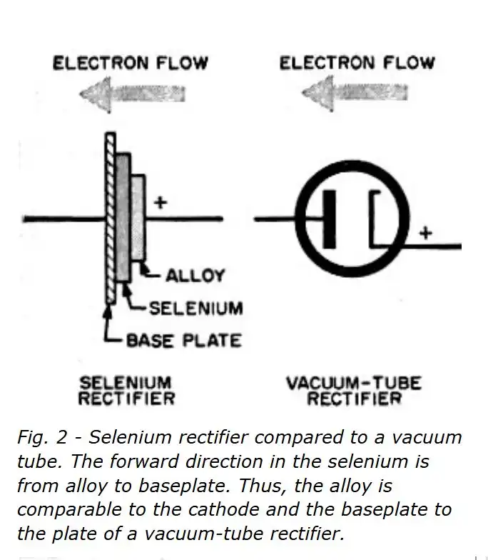
Selenium rectifiers do not use doped PN junctions like modern silicon or germanium diodes. Instead, they operate using a metal–semiconductor junction with a naturally formed barrier oxide layer. The result is a one-way conduction effect similar to a diode, but achieved through different means.
| Feature | Description |
|---|---|
| Voltage drop | ~1V per cell (higher than silicon or germanium) |
| Reverse leakage | Higher than modern PN diodes |
| Efficiency | Lower due to forward drop and heating |
| Durability | Very rugged; can withstand overloads |
| Recovery time | Slow (not suitable for high-frequency use) |
| Common Uses | Vintage TVs, battery chargers, early power supplies |
Selenium rectifiers are built from multiple thin metal–selenium cells stacked in series. This design is not just mechanical — it improves the electrical performance in several ways:
Many stacks also include cooling fins or air gaps between plates to improve heat dissipation during high-load operation.
Selenium rectifiers operate through a metal–semiconductor junction with a critical oxide layer (SeO₂), not by PN junctions. Though largely obsolete today, they played an essential role in early power electronics before being replaced by silicon diodes.
Selenium (Se) is a nonmetallic element with semiconducting properties, historically used in:
Though largely obsolete today, selenium devices were durable and important milestones in early semiconductor development.
Selenium photocells — also known as selenium solar cells or barrier-layer photodiodes — convert light into electricity using a metal–semiconductor junction. Unlike silicon solar cells that use a doped PN junction, selenium cells depend on the natural photoelectric properties of selenium.
When light strikes the selenium layer, it excites electrons into the conduction band. These photo-generated carriers are separated by the internal barrier layer (SeO₂), producing a voltage across the cell. The result is a small direct current when connected to a load.
| Property | Typical Value / Note |
|---|---|
| Open-circuit voltage | ~0.4 to 0.6 V |
| Current output | Microamps to milliamps depending on size and illumination |
| Spectral response | Peak at ~550–600 nm (green light) |
| Response time | Slow (~milliseconds) compared to silicon photodiodes |
| Efficiency | Low (~1% or less) |
| Durability | Excellent; stable for decades under normal use |
Selenium photocells are barrier-layer photovoltaic devices that predate silicon solar cells. Though inefficient by modern standards, they were widely used for decades due to their simplicity and reliability. Their construction is more closely related to selenium rectifiers than to modern PV cells.
Early triodes (De Forest’s Audion, 1906–1907) were “gassy” soft-vacuum devices. True reliability arrived only after high-vacuum practice matured (Langmuir at GE, c. 1913–1915): hard vacuums, an internal getter to mop up residual gas, and efficient heated cathodes (thoriated tungsten or oxide-coated) with a separate heater. That combination made stable amplification, oscillators, and long tube life practical.
Thermionic emission depends on temperature and work function. To reduce heater power and improve life, industry moved from bare tungsten to thoriated tungsten and then to oxide-coated cathodes (barium/strontium/calcium oxides on nickel).
| Cathode system | Typical composition | Operating temp (≈K / °C) | Pros | Trade-offs |
|---|---|---|---|---|
| Pure tungsten (directly heated) | W filament | ~2700–2900 K (≈2400–2600 °C) | Rugged, early standard | High power, dull emission efficiency, microphonics in battery sets |
| Thoriated tungsten (directly heated) | W with ThO2 | ~1800–2000 K (≈1500–1700 °C) | Lower work function than W; visible orange glow; classic RF power tubes | Still hot & power-hungry vs. oxides |
| Oxide-coated (indirectly heated) | Ni sleeve with Ba/Sr/Ca oxides + separate heater | ~800–1100 K (≈500–830 °C) | High emission at low temp; low heater power; electrically quiet | Oxide can be poisoned by contamination/ion bombardment |
Correct. Lead-through pins must match the glass’s coefficient of thermal expansion (CTE) so the seal stays in compression as it cools; a mismatch puts the glass in tension and cracks the bulb. This is the core rule of glass-to-metal sealing. :contentReference[oaicite:0]{index=0}
| Glass family | Common pin / lead alloys | Why these alloys |
|---|---|---|
| “Soft” glasses (soda-lime / lead) | Dumet (Cu-clad Ni-Fe ~42) · Alloy 52 (Ni ~50%, Fe balance) | Dumet’s Ni-Fe core gives low CTE; copper sheath aids sealing and conductivity. Alloy 52 is a controlled-expansion Ni-Fe for soft-glass seals. :contentReference[oaicite:1]{index=1} |
| “Hard” glasses (borosilicate) | Kovar / Fernico (Fe-Ni-Co) · sometimes Alloy 42 / Invar-family | Kovar’s CTE is closely matched to borosilicate, enabling hermetic, shock-resistant seals; 42-alloy/other Ni-Fe grades are used in specific matched-seal designs. |
Each part of a vacuum tube required metals with specific properties: high melting points, low vapor pressure (so they wouldn’t evaporate into the vacuum), good electrical conductivity, and sometimes catalytic or emissive qualities. Below is a summary of the most common materials.
The key selection rules were: high melting point (withstand heat), low vapor pressure (so metals wouldn’t evaporate inside the vacuum), low secondary emission (to prevent instability), and chemical compatibility with the glass and cathode coatings.
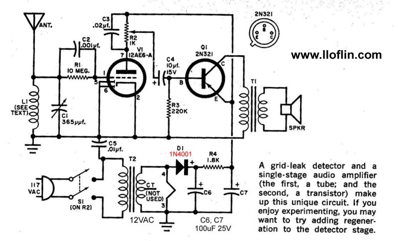
Basic triode vacuum tube circuit.
Vacuum tubes, driven by electron flow from negative to positive, were the backbone of early electronics, as in my electron flow model. This page explores their operation, applications, and niche revival, building on my selenium and cesium discussions.
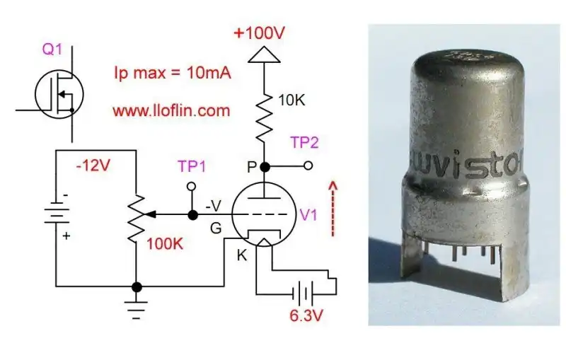
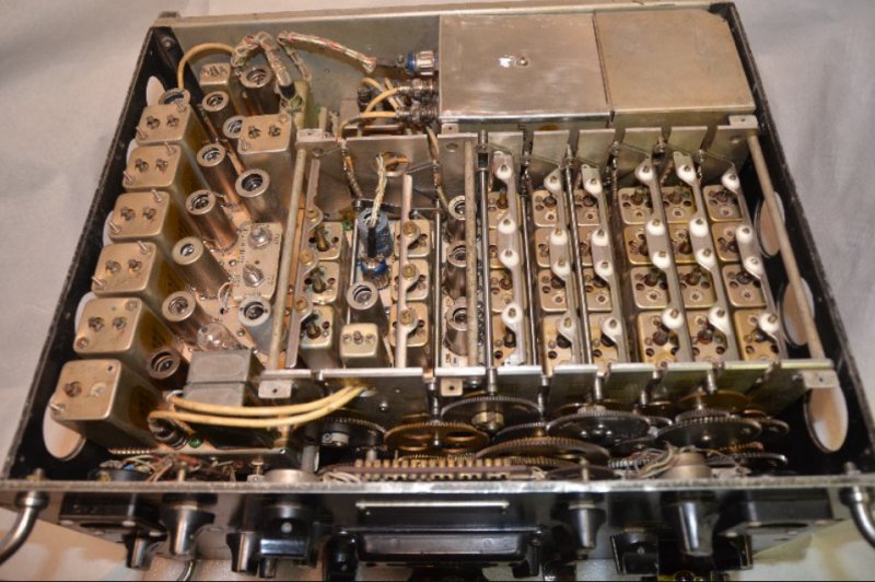
Above is a vacuum tube triode used for RF amplification in early television tuners, marketed as a Nuvistor. To quote:
The Nuvistor vacuum tube was invented by RCA (Radio Corporation of America). It was announced in 1959 as a type of vacuum tube designed to compete with the then-emerging bipolar junction transistors.
Nuvistors were compact and reliable, but transistors surpassed them by the 1970s due to cost and efficiency.
Vacuum tubes are used in numerous applications, including RF and audio amplifiers, voltage rectifiers, and voltage regulators.
They operate by thermionic emission, where a metal (cathode) is heated, "boiling" off electrons in a vacuum. In a vacuum, electrons move freely without air resistance, filling the space.
A positively charged metal plate (anode) attracts the electrons to move to the positive side of the power supply. This anode or plate supply voltage can be hundreds or 12 volts with late-designed "space charge" tubes for car radios.
With a plate and cathode alone, the vacuum tube operates as a rectifier due to charges moving in one direction, from cathode to anode (plate).
When a mesh electrode or "grid" is placed between the cathode and plate, a negative charge relative to the cathode controls the level of electron flow. This configuration is called a triode, and it operates as an amplifier.
By varying the voltage on the grid, you can either attract or repel electrons. A negative voltage on the grid repels electrons, reducing the current to the anode. A positive voltage on the grid attracts electrons, allowing more current to pass to the anode.
Small changes in the grid voltage can cause large changes in the anode current, which is the basis for amplification in vacuum tubes. This is because the grid modulates the electric field, controlling a large number of electrons with relatively small voltage changes, as in my electron flow model.
Early vacuum tubes used the heater (or filament), a hot tungsten wire, as a cathode. Later designs used a separate cathode isolated from the filament used only as a heater, with modern coatings (e.g., barium oxide) lowering operating temperatures.
Heat management is critical. Heat is needed at the cathode (~800–1200°C) to allow the emission of electrons. However, heat is also created at the plate (anode), particularly with beam power tubes, which can exceed 1000°C. Examples include audio output tubes in guitar amplifiers and horizontal and vertical output tubes in vacuum tube televisions. Cooling methods like fins or forced air are often required.
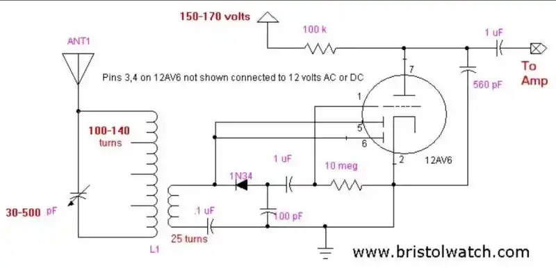
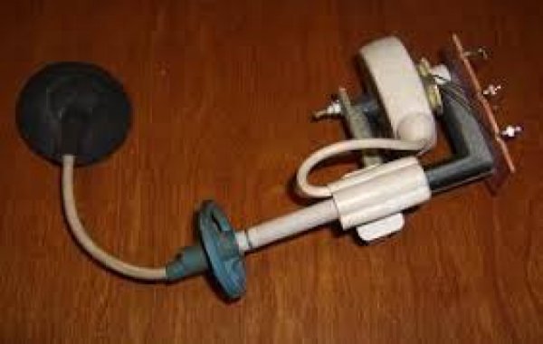
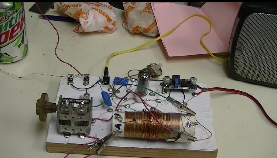
12AV6 Vacuum Tube Radio
Vacuum tube applications didn’t end overnight, as it took several years for solid-state to develop. In car radios, where 12-volt operation "space charge" vacuum tubes flourished, the audio power outputs were PNP germanium transistors, while small signal radio frequency circuits were still "space charge" type vacuum tubes. Even those would be replaced by transistors when prices came down.
In vacuum tube televisions, low-power RF and audio circuits adopted solid-state first, while high-power output tubes persisted longer.
Vacuum tube rectifiers gave way to selenium rectifiers, later replaced by silicon B+ rectifiers, as discussed in my selenium rectifiers.
Types of Tubes:
Diode: Simplest form with just a cathode and anode, used for rectification.
Triode: Adds a grid for control, used for amplification.
Tetrode/Pentode: Additional grids for better performance (like reducing unwanted capacitance effects).
Beam Tetrode: Used in audio power amplification, e.g., 6L6 in guitar amps.
As of 2025, tubes are used in high-power RF transmitters, military EMP-resistant systems, and audiophile equipment.
The electron was discovered in 1897 by J.J. Thomson during his experiments with cathode rays.
Vacuum Tube History:
1883: Edison discovers thermionic emission.
1904: Fleming develops the first vacuum diode.
1906: De Forest invents the triode Audion tube.
1920s–1940s: Vacuum tubes dominate electronics industry.
1947: Transistor is invented, leading to tube decline.
1950s–1960s: Peak usage in computers (e.g., ENIAC).
2000s: Revival in audio and display applications.
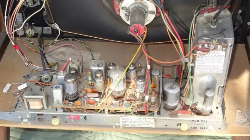
Vacuum tube Black and White television chassis.
Click for a larger image.
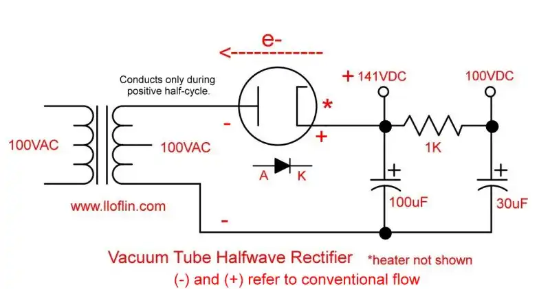
Vacuum tube diode half wave power supply.
Click for larger image.
Yes, vacuum tube amplifiers are still made for musicians, though the industry has changed in recent years.
Production: Vacuum tubes are still made, but in smaller quantities. Factories in Russia (e.g., Svetlana), China (e.g., PSVANE), Slovakia (e.g., JJ Electronic), and the USA (Western Electric in Georgia) produce tubes. The closure of Shuguang in 2019, Russian export restrictions, and a 2021 Chinese factory fire impacted supply.
Demand: Vacuum tubes are used in high-end guitar amplifiers and stereo equipment. Audiophiles and audio engineers praise tube gear for its rich midrange and extended frequency response.
Manufacturers: Companies like Audio Hungary, Audio Research, and Western Electric produce vacuum tube amplifiers. Boutique brands (e.g., TAD, Mullard reissues) cater to musicians.
Designers: Japanese designers like Ken Shindo are known for their vacuum tube amplifiers.
Niche Markets:
Audio Equipment: Audiophiles and musicians prefer tube amplifiers for their warm, harmonic distortion.
High-End Electronics: Used in preamps and power amps.
Radio Transmitters: Used in some broadcasting stations.
Military/Industrial: Resistant to EMPs and radiation, used in military and space applications.
Challenges: High prices and limited supply due to niche production. Ongoing research aims to improve tube longevity and efficiency.
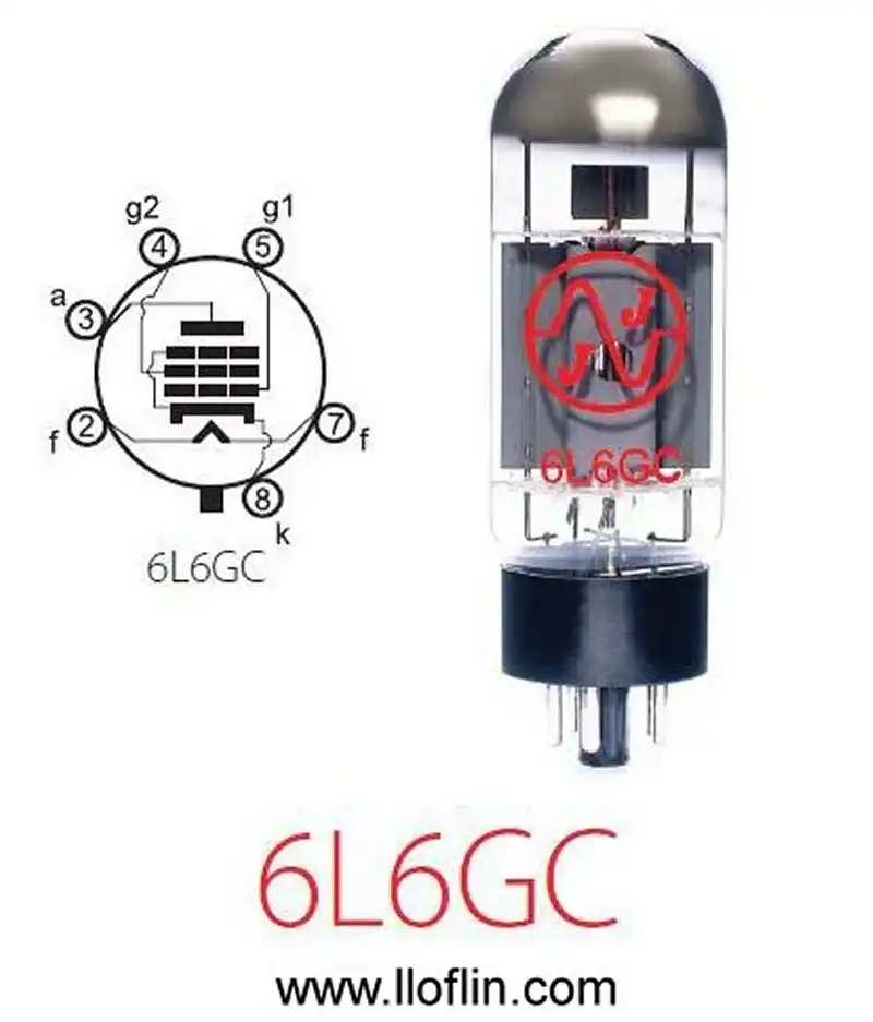
6L6 vacuum tube power pentode.
The 6L6 is a popular power output tube. As of December 19, 2024, a "Brand New Current Matched Quad (4) Electro-Harmonix 6L6GC Vacuum Tubes" is advertised on eBay for $170. Four used and tested 6L6s cost $51.
Answer: Based on information from various sources, including online marketplaces and discussions on X, the cost of a 6L6 vacuum tube can vary significantly based on brand, condition (new old stock vs. new production), and specific type (e.g., 6L6GC, 6L6G, etc.). Here's a general overview:
NOS (New Old Stock) Tubes: These can be quite expensive due to their rarity and preferred sound characteristics by audiophiles and musicians. For instance, an NOS RCA Black Plate 6L6GC might go for around $349.99 per tube, as seen from specialized vacuum tube sellers.
Current Production Tubes: New production tubes are generally less expensive than NOS. For example, a Sovtek 6L6WXT+ might be priced around $29.99 to $39.99 per tube, depending on the seller and any additional features like low noise or microphonics.
Special Variants and Brands: Prices can fluctuate with tubes like the 7581A Philips ECG Sylvania, which might be priced around $39.99 per tube, indicating that specialized or branded versions could command different prices even among current productions.
Market Sentiment from X: While specific prices aren’t directly quoted from X posts, there’s an indication of shock over high prices, suggesting that some 6L6 tubes might be listed or discussed at prices that users find surprisingly high, like several hundred dollars.
General Market Observation: From both the search results and X posts, it’s clear there’s a wide range for pricing. Vintage or highly sought-after models can reach into the hundreds of dollars per tube, while modern productions from current manufacturers might be available for much less, appealing to a broader user base.
Remember, these prices are indicative and can vary based on where you’re buying from, the condition of the tube, its rarity, and its audio characteristics. If you’re looking to purchase, it would be wise to check multiple sources for the best deal or to ensure you’re getting the specific type of 6L6 tube you need for your equipment or collection. Prices remain volatile in 2025 due to supply chain issues and rising demand.
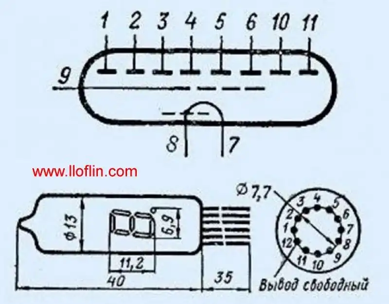
Vacuum Fluorescent Display Pin Connections
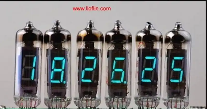
Vacuum Fluorescent Display
Vacuum tubes, from diodes to VFDs, rely on electron flow from negative to positive, as in my electron flow model. While largely replaced by solid-state, their legacy persists in audio, military, and retro applications. Explore my training program, circuit projects, or YouTube videos.
Negative Differential Resistance occurs when, over a specific range of voltages, increasing the voltage causes the current to decrease. This behavior appears in nonlinear devices and is different from the idea of a component having a fixed "negative resistance."
This is not true “negative resistance” like a power source. It’s a local, nonlinear behavior — a negative differential resistance over part of the V–I curve, not the whole device.
Imagine pushing a cart: normally, more force = more speed. But at a certain point, adding more force slows it down. That’s how NDR works — only over a specific range.
Note: This effect is real, measurable, and used in practical circuits like oscillators and voltage regulators.
Despite the name, negative resistance doesn’t mean a resistor with a negative value. Instead, it's a way to describe a device that behaves differently under certain conditions—as current increases, the voltage across it goes down.
Ohm’s Law:
V = I × R
More current → more voltage drop.
That’s positive resistance (like a resistor, heater, wire).
It’s about the slope of a voltage–current graph:
ΔV / ΔI) becomes negative| Device | Description |
|---|---|
| Xenon Flash Tube / Neon Bulb | After ignition, voltage drops as current rises |
| Tunnel Diode | Has a “dip” in its voltage-current curve |
| Gunn Diode | Used in microwave circuits for oscillators |
| Unijunction Transistor (UJT) | Used for triggering in timing circuits |
Voltage (V)
  |
  |       /\
  |      /  \
  |     /    \_________
  |    /               \
  |___/                 \____> Current (I)
       ↑
   Negative resistance region (slope ↓)
In this middle section, more current actually causes voltage to drop. That’s what we call negative resistance.
These devices are used in oscillators, flashing lights, trigger circuits, and microwave systems. They can self-oscillate or sustain pulses, useful in timing or signal generation.