My 74C14 based pulse generator. Larger Image Visit Hobby Page
My 74C14 based pulse generator. Larger Image Visit Hobby Page
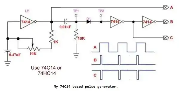
This circuit is a simple variable-frequency pulse generator built using a Schmitt-trigger inverter (such as the 74C14 or 74HC14). It creates a clean digital square wave suitable for driving digital logic, microcontroller timer inputs, or acting as a general-purpose test signal source.
The inverter and RC network form an astable oscillator. The capacitor charges and discharges through the resistor, and the inverter switches state when the voltage crosses its threshold due to the Schmitt-trigger input. This generates a repetitive pulse.
The waveform is then cleaned and reshaped through additional 7414 stages and a diode-capacitor shaping network. The outputs labeled A, B, and C show the waveform at different points:
The correct timing behavior of this oscillator, as built and tested, follows the empirical formula:
f = 1 / (2 × T), where T = R × C
This is based on real-world testing and differs significantly from textbook approximations like f ≈ 1 / (1.4 × R × C), which can be misleading for Schmitt-trigger-based oscillators.
For full validation and scope traces, refer to:
https://www.bristolwatch.com/ele2/sn7414_osc.htm
TMR0 or TMR1 as external clocksThe CD4093 CMOS quad 2-input NAND gate can also be used in place of the 74C14/74HC14. It contains Schmitt-trigger inputs, and one of the NAND gate inputs can serve as an enable/disable control line for turning the oscillator on or off, making it a versatile choice for applications requiring gating.
Use a 74C14, 74HC14, or CD4093 depending on logic level requirements and desired gating features.

74C14 Schmitt trigger based pulse generator and switch debounce circuit.
Larger image |
Visit Hobby Page
