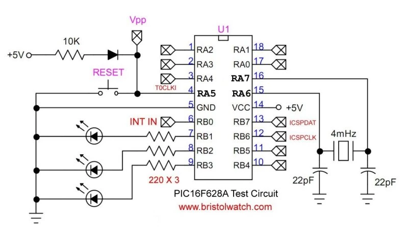
PIC16F628A test setup uses internal oscillator in these projects.
No Crystal with Switches Schematic | Visit Hobby Page
No Crystal with Switches Schematic | Visit Hobby Page
by Lewis Loflin
This example shows how to use the PIC16F628A’s RB port change interrupt to detect and debounce a button press on RB4. The button connects between RB4 and ground, with the internal pull-up enabled. A 120Ω resistor is added in series with the switch to protect the pin if misconfigured as an output.
When the button is pressed and stable for 20 ms, an LED on RB1 toggles.
On the PIC16F628A, interrupt-on-change (IOC) for PORTB (RB4–RB7) triggers on any level change—both press (high→low) and release (low→high) generate interrupts. To detect only a button press, check if the pin (e.g., PORTBbits.RB4) is low in the ISR. The ISR must also read PORTB to clear the mismatch and then clear RBIF. If you want to detect edges (e.g., falling only), store the previous state and compare it with the current one. Pressing RB5 will still trigger the ISR, so your logic must ignore it if not used. This avoids unwanted double responses per press.
#include <xc.h>

// CONFIG
// Use internal 4 MHz oscillator,
// RA6 and RA7 are digital I/O
#pragma config FOSC = INTOSCIO
#pragma config WDTE = OFF
#pragma config PWRTE = ON
#pragma config MCLRE = OFF
#pragma config BOREN = OFF
#pragma config LVP = OFF
#pragma config CPD = OFF
#pragma config CP = OFF

#define _XTAL_FREQ 4000000UL

// Global flag for button press
// volatile for use in ISR
volatile unsigned char buttonPressed = 0;
volatile unsigned char dummy = 0; // see page 38

void __interrupt() isr(void) {

// debounce delay
if (INTCONbits.RBIF) __delay_ms(20);

if (PORTBbits.RB5 == 0) { // ignore RB5
    dummy = PORTB;  // clear mismatch
    INTCONbits.RBIF = 0;               // clear interrupt flag
    return;                            // skip rest of ISR
    } // end RB5

if (PORTBbits.RB4 == 0) {
    buttonPressed = 1;  // flag set for main loop

    // Wait until button is released
    while (PORTBbits.RB4 == 0)
        ;  // do nothing

    // Required: read PORTB to clear mismatch condition
    dummy = PORTB;
    INTCONbits.RBIF = 0;  // clear interrupt flag
} // end RB4


} // end ISR

void main(void) {
    CMCON = 0x07; // comparators off
    // Setup I/O
    TRISB = 0b11110000;     // RB4–RB7 inputs, RB0–RB3 outputs
    PORTB = 0x00;
    OPTION_REGbits.nRBPU = 0;  // enable internal pull-ups on PORTB
    // Enable interrupts
    INTCONbits.RBIF = 0;    // clear PORTB change flag
    INTCONbits.RBIE = 1;    // enable RB change interrupt
    INTCONbits.GIE = 1;     // enable global interrupts

    while (1) {
        if (buttonPressed) {
            PORTBbits.RB1 ^= 1;  // toggle LED on RB1
            buttonPressed = 0;   // clear flag
        } // end button
    } // end while
} // end main
Hardware Notes:
nRBPU = 0Mechanical switches bounce when pressed, causing multiple false triggers. This example uses software debounce by adding a short delay (__delay_ms(20)) inside the interrupt-on-change ISR for RB4 and RB5 on the PIC16F628A. It’s simple, effective, and doesn’t require extra components—ideal for educational demos. For faster or more reliable input handling, a hardware debounce circuit using a 74C14 Schmitt trigger is preferred. It cleans up switch signals before they reach the microcontroller, eliminating the need for software delays and improving responsiveness. Software debounce is fine for basic applications; hardware is better for precision or noisy environments.
MCLRE = OFF turns RA5 into a digital I/O pin; disables external reset.