
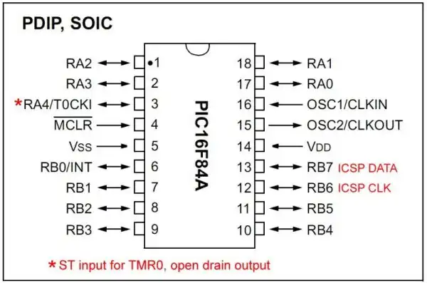
PIC16F57 24-pin DIP package.
Click for larger image. Wiring schematic Visit Hobby Page
by Lewis Loflin
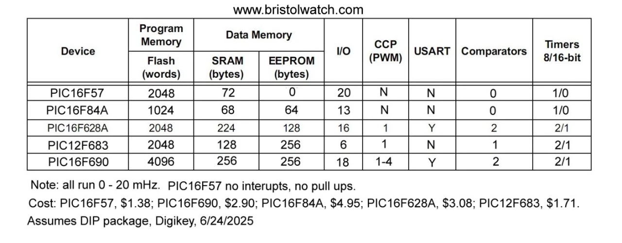
This page cover using and setting up the PIC16F57. It is very basic, inexpensive, and great for testing hardware. Hardware is the focus here.
The next project in the link below uses the PIC16F57 microcontroller to count from 0 to 255, displaying both the binary and decimal values on an HD44780-compatible LCD. The counter updates every 500 milliseconds using TMR0 driven by an external 60 Hz timebase. It’s a straightforward hardware test designed to verify the PIC16F57's function, explore its quirks (such as the 2-level call stack), and demonstrate practical embedded development — with no simulation software involved.
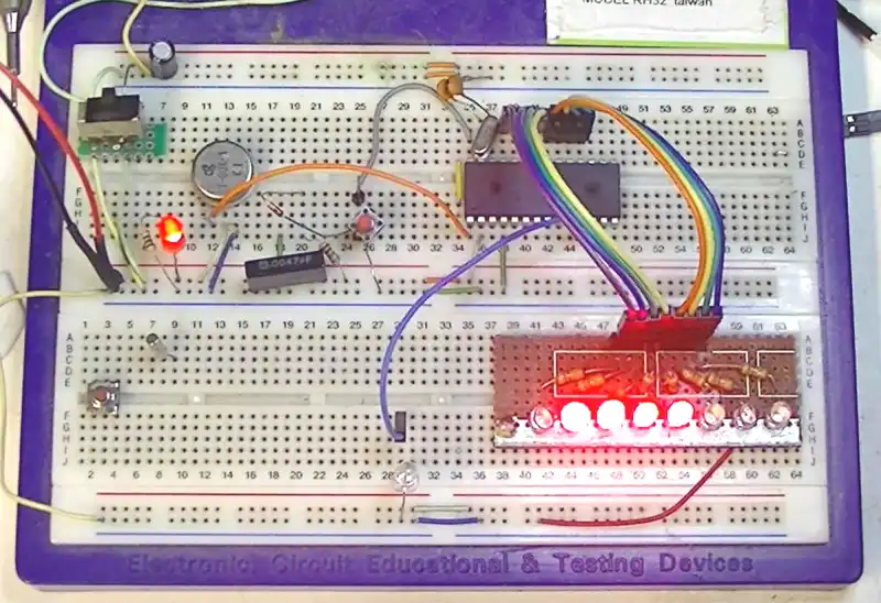
Every aspect of this circuit is tested on real hardware. No guesses, no virtual models — just measurable, observable behavior. This is not a sandbox — it’s a lab.
See 8-Bit LCD Interface with PIC16F57: Binary and Decimal Counter in C (XC8)
The PIC16F57 is perfect for testing eight-bit hardware and that is the focus with these projects.
Many visitors to this site attempt to simulate these circuits using SPICE-based tools or drag-and-drop simulators — and then wonder why they don’t work. Here's the reality:
If you're serious about learning how electronics actually work — build it, measure it, break it, and fix it. That’s what I do here.
This isn’t a sandbox. It’s a lab.
A perfect example of why simulation isn’t enough: the PIC16F57 has a fixed two-level return stack. That means it can only remember the return addresses for two nested subroutine calls.
See PIC16F57 Serial LCD and 4x4 Keypad Demo
This isn’t just a technical detail — it can cause program crashes, missed returns, or corrupt behavior if you nest more than two calls. And the worst part?
I would never have spotted this unless I actually ran a program and debugged it. The simulator didn’t show it — the hardware did.
If you're using chips like the 16F57, you must test on real hardware to find these hidden limitations. Simulators won't show stack overflows, pin conflicts, or timing glitches — only live debugging will.
Test it. Watch it fail. Learn why — and fix it.
What works on the PIC16F57
| File Address | Register |
|---|---|
| 00h | INDF(1) |
| 01h | TMR0 |
| 02h | PCL |
| 03h | STATUS |
| 04h | FSR |
| 05h | PORTA |
| 06h | PORTB |
| 07h | PORTC |
| 08h – 1Fh | General Purpose Registers |
(1)INDF is not a physical register; it is used with FSR for indirect addressing.
Note 1: INDF is not a physical register. See Section 3.7, "Indirect Data Addressing; INDF and FSR Registers."
CLRF PORTB        ; Clear PORTB
MOVLW 0x00
TRIS PORTB        ; Set all PORTB pins as output

CLRF PORTC
TRIS PORTC        ; Set all PORTC pins as output

CLRF PORTA
MOVLW 0x0F
TRIS PORTA        ; Set lower 4 bits of PORTA as input (RA0–RA3)
These configure I/O direction but do not occupy memory addresses. This is why they do not appear in the register file map.
OPTION instruction (or OPTION_REG in newer PICs). This sets up the prescaler, TMR0 edge, but has no direct file address.In all of my assembly programs, I make it a rule to clear PORTA, PORTB, and PORTC during initialization — even if they are not used.
This avoids potential problems caused by unpredictable startup states or leftover values from resets. Uninitialized ports may float, latch, or output spurious logic levels, which can interfere with proper operation or downstream hardware.
CLRF PORTA
CLRF PORTB
CLRF PORTC
Note: This is especially important on older devices like the PIC16F54 or PIC16F57, where all ports are digital and have no analog fallback or default behavior.
by Lewis Loflin
See PIC16F57 wiring connections.
This project uses the PIC16F57 to generate a binary count (0–255) on PORTC, updating every 500 milliseconds. This is a basic test to confirm that the microcontroller, crystal oscillator, and PORTC outputs are functioning properly.
See Zero-Crossing Detectors Circuits and Applications
See Improved AC Zero Crossing Detectors for Arduino
T0CLKI (pin 1) is the TMR0 external clock input. It has a Schmitt trigger input. Must be tied to VSS or VDD, if not in use, to reduce current consumption.
T0CKI (pin 1) is Schmitt Trigger clock input to Timer0. Must be tied to VSS or VDD, if not in use, to reduce current consumption.
Two level hardware stack, operating voltage 2V - 5.5V.
// 8 LEDs on PORTC
// PIC16F57 C Version: Count 0–255 (binary) on PORTC with 500ms delay
// Assumes external 4 MHz crystal
// 51 bytes program 12 bytes SRAM with MPLAB X and C8.

#include <xc.h>
// Configuration bits
#pragma config WDT = OFF   // Watchdog Timer disabled
#pragma config CP = OFF     // Code protection off
#pragma config OSC = XT    // XT Oscillator (use 4 MHz crystal)

#define _XTAL_FREQ 4000000UL

void INIT57(void)   {
    // TRIS settings
    // TRISA = 0x0F; // Lower 4 bits as input, upper bits output
    // TRISB = 0xFF; // All input
    TRISC = 0x00; // All output

    // Clear all ports
    PORTA = 0x00;
    PORTB = 0x00;
    PORTC = 0x00;
}

void main(void) {
    INIT57();
    unsigned char counter = 0;
    while (1) {
        PORTC = counter;
         __delay_ms(500);
        counter++;
    }
}
This example uses only 8 output pins and very little flash or SRAM. It’s ideal as a first test when evaluating a PIC16F57 for 8-bit digital output applications.
| Feature | PIC16F84A | PIC16F628A |
|---|---|---|
| Pull-Up Enable Bit | OPTION_REG, bit 7 = RBPU0 = pull-ups enabled |
Same: OPTION_REG, bit 7 = nRBPU (name inverted but function identical) |
| RB0 External Interrupt | Yes, on edge | Yes, same functionality |
| RB4–RB7 Interrupt-on-Change | Yes | Yes, identical |
| IO Direction Control | TRISB |
TRISB (same) |
Common register control using C-style bitwise logic:
| Operation | Purpose | Example |
|---|---|---|
|= |
Set bit n to 1 (make high) |
PORTB |= (1 << 2); |
&= ~(1 << n) |
Clear bit n to 0 (make low) |
TRISB &= ~(1 << 3); |
^= |
Toggle bit n (flip state) |
PORTB ^= (1 << 0); |
These are especially useful when working with individual I/O pins without affecting other bits in a register.
#pragma is used to send special instructions to the compiler. In XC8, it's mainly used to set configuration bits (fuses) directly from your C source code.
| Directive | Meaning |
|---|---|
#pragma config FOSC = XT |
Use external crystal oscillator |
#pragma config WDTE = OFF |
Disable watchdog timer |
#pragma config MCLRE = OFF |
Disable MCLR (RA5 becomes I/O) |
#pragma config LVP = OFF |
Disable low-voltage programming |
These lines are essential for ensuring your microcontroller starts up with the correct hardware settings. Without them, you'll rely on manual IDE configuration — and that can lead to mismatched builds.
Bit Manipulation Macros:#define bitset(var, bitno) ((var) |= (1 << (bitno))) // Set bit #define bitclr(var, bitno) ((var) &= ~(1 << (bitno))) // Clear bit #define bitflip(var, bitno) ((var) ^= (1 << (bitno))) // Toggle bit #define bitcheck(var, bitno) (((var) & (1 << (bitno))) != 0) // Check bit
_XTAL_FREQ and Delay Macros in XC8To use __delay_ms() and __delay_us() in MPLAB XC8 projects, you must define the system clock frequency using _XTAL_FREQ as an unsigned long.
#include <xc.h>

// Configuration bits
#pragma config WDT = OFF   // Watchdog Timer disabled
#pragma config CP = OFF     // Code protection off
#pragma config OSC = XT    // XT Oscillator (use 4 MHz crystal)

#define _XTAL_FREQ 4000000UL  // Required: 4 MHz crystal, note the UL!

void main(void) {
    TRISB = 0x00;      // PORTB output
    PORTB = 0x00;

    while (1) {
        PORTB ^= 0x01;  // Toggle RB0
        __delay_ms(500);  // 500ms delay
    }
}_XTAL_FREQ must be defined before any __delay_xx() macros are used.UL suffix (e.g., 4000000UL) to ensure correct arithmetic.__delay_ms(x) and __delay_us(x) are built-in macros, not functions.UL → Wrong delay or compiler errors_XTAL_FREQ after delay use → fails silentlyCompiled with XC8 for PIC16F57, these code snippets toggle LED on RB1. Measured flash usage illustrates macro efficiency:
| Code | Flash Used | Notes |
|---|---|---|
PORTBbits.RB1 ^= 1; |
67 bytes | Standard bit toggle, safe and readable |
PORTBbits.RB1 = PORTBbits.RB1 ^ 1; |
66 bytes | Explicit XOR form; minor gain |
LED = LED ^ 1; |
66 bytes | Macro hides bit expression |
bitflip(PORTB, 1); |
58 bytes | ✅ Most efficient — direct XOR via macro |
Macro used:
#define bitflip(var, bitno) ((var) ^= (1 && (bitno)))
Conclusion: For size-critical code, direct macros like bitflip() save valuable flash on baseline PICs such as the 16F57.
int8_t and int16_t in Embedded C
The types int8_t and int16_t are part of the <stdint.h> header and define fixed-width signed integers. These are essential in embedded systems where memory and data width must be tightly controlled.
| Type | Size | Range | Description |
|---|---|---|---|
int8_t |
8 bits | -128 to +127 | Signed 8-bit integer (1 byte) |
uint8_t |
8 bits | 0 to 255 | Unsigned 8-bit integer |
int16_t |
16 bits | -32,768 to +32,767 | Signed 16-bit integer (2 bytes) |
uint16_t |
16 bits | 0 to 65,535 | Unsigned 16-bit integer |
The DS18B20 sensor returns a 16-bit signed value that must be interpreted correctly. This is why we use:
int16_t temp;     // Holds raw 16-bit signed temperature from DS18B20
int8_t whole;     // Stores the integer (whole °C) part of the temperature
uint8_t frac;     // Stores the fractional part (in tenths of a degree)
For example, if the sensor returns 0x00A2, that equals 162 / 16 = 10.125°C. The code separates this into:
whole = 10frac = 1 (tenths of a degree)Using these types ensures accurate, portable temperature display on an LCD or serial output.