
PIC16F57 24-pin DIP package.
Click for larger image. Wiring schematic Visit Hobby Page
Electric current is the movement of electric charges through a conductor or medium.
This definition reflects the actual physical motion of charges, not the historical “conventional current” direction.
by Lewis Loflin
In this lesson, we explore the real-world behavior of AC rectification circuits — including RMS, peak, and average voltage relationships in half-wave and full-wave rectifiers. Going beyond textbook theory, we analyze diode and SCR voltage drops as they truly occur — after waveform rectification — and show how incorrect assumptions can lead to measurable voltage errors. Whether you're studying electronics or teaching it, this guide delivers practical insights rooted in hands-on testing and physical science.
From my YouTube video SCRs Theory and Circuits I got the following question:
Question: According to your calculations the average voltage for full wave rectified = 0.90*RMS (assuming ideal diodes). That can’t be right… RMS voltage and DC voltage of the same value across a resistor will both have identical power dissipation. RMS is average, I thought. You say the average voltage for half wave rectified is half the full wave voltage, which makes sense.
RMS (Root Mean Square) is a statistical measure used to express the effective or equivalent value of a varying (AC) waveform — especially voltage or current.
For AC signals, RMS represents the amount of DC power equivalence. It tells us the equivalent DC value that would produce the same power dissipation in a resistive load.
RMS Voltage (Vrms) = Vpeak × 0.707
RMS Current (Irms) = Ipeak × 0.707
Where Vpeak or Ipeak is the maximum (peak) value of the waveform.
P = Vrms × IrmsIn household AC systems (like 120V or 230V AC), that voltage is an RMS value. The peak voltage is actually higher:
120V RMS → ~170V Peak
230V RMS → ~325V Peak
RMS is the standard for AC measurement because it represents usable, real-world energy.
Goal: Understand how to convert between RMS, peak, and average voltages or currents in a sinusoidal AC waveform — particularly in the context of rectifiers.
Vpeak = VRMS × √2Vpeak = VRMS × 1.414
Vavg = Vpeak × (2 / π)Vavg ≈ Vpeak × 0.637
Vavg = VRMS × 1.414 × 0.637Vavg ≈ VRMS × 0.9
If you have 120V RMS from the wall:
| Conversion | Formula | Approx. Factor |
|---|---|---|
| RMS → Peak | RMS × √2 |
× 1.414 |
| Peak → Average | Peak × (2 / π) |
× 0.637 |
| RMS → Average | RMS × √2 × (2 / π) |
× 0.9 |
Note: These values are valid for pure sine waves only. For other waveforms (square, triangle, etc.), the ratios will differ.
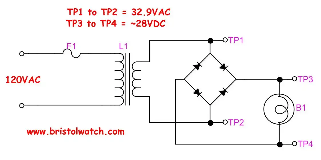
When calculating the DC output from rectified AC (such as in full-wave or bridge rectifiers), it's important to apply diode or SCR voltage drops after computing the ideal DC voltage — not before.
VDC = (VRMS × 0.9) − Vdrop
Vdrop ≈ 1.4 V (two diode drops)Vdrop ≈ 0.7 V (one diode per cycle)VDC = [(Vpeak − Vdrop) × 0.637]
This results in underestimating the output voltage.
In testing, using the incorrect method resulted in a voltage error of −0.45 V. Using the correct approach — subtracting diode drops after calculating VRMS × 0.9 — matched the measured output precisely.
This reinforces the importance of understanding when and how voltage drops affect the output in rectifier circuits. Apply voltage drop corrections only at the output stage — not before calculating the average DC level.
Vpeak = VRMS × √2 ≈ VRMS × 1.414Vavg = Vpeak × 0.637Vavg ≈ VRMS × 1.414 × 0.637 ≈ VRMS × 0.9In half-wave rectification, we lose half of the waveform. So we divide the full-wave average by 2:
Vavg ≈ VRMS × 0.9 / 2VRMS = 120V → Vavg ≈ 54V (ignoring losses)If using an SCR in conduction mode, consider:
0.6V1.2VFull-wave: Vavg ≈ VRMS × 0.9Half-wave: Vavg ≈ VRMS × 0.9 / 2Vavg when accuracy mattersWhile the typical silicon diode forward voltage drop is cited as ~0.7 V, actual values can vary significantly based on type, construction, and current. In power applications, drops as low as 0.5 V are common.
| Diode Type | Typical Vf @ Rated Current | Notes |
|---|---|---|
| Standard Silicon Diode (1N4001, etc.) | 0.6–1.1 V | Vf increases with current and temperature |
| Fast Recovery Rectifier | 0.9–1.5 V | Lower recovery time, higher Vf |
| Power Silicon Diode (e.g., 6A10) | 0.5–0.8 V | Designed for low Vf at high current |
| Schottky Diode (e.g., 1N5822) | 0.2–0.5 V | Fast switching, low Vf, limited voltage rating |
When working with power rectifiers, check the datasheet graph for IF vs. VF. At 1 A, a 6A10 might drop 0.55 V — far lower than expected for a silicon diode. Don't guess — measure or read the specs!
| Device | Typical Forward Voltage Drop | Notes |
|---|---|---|
| Silicon Diode | ~0.6V – 0.7V | 0.6V is commonly used for educational calculations. |
| SCR (Thyristor) | ~1.2V – 1.7V (latched on) | 1.2V is a solid approximation for most SCRs under load. |
SCR datasheets define VTM (on-state voltage drop) under specific conditions (e.g., 1.2V @ 10A). The drop can vary:
Assuming 0.6V for diodes and 1.2V for SCRs is ideal for teaching:
This approach emphasizes clarity and functionality over precision — perfect for classroom or YouTube instruction.
In CRT televisions and modern power supplies, special-purpose diodes are used to handle the demands of high-speed switching and significant current flow.
| Part Number | VRRM | IF(avg) | VF @ IF | Package |
|---|---|---|---|---|
| UF5408 | 1000 V | 3 A | ~1.0 V @ 3 A | DO-201AD |
| MB6S (bridge) | 600 V | 0.5 A | ~1.1 V per leg | SIP-4 |
| MBR2045CT | 45 V | 20 A | ~0.55 V | TO-220 |
These diodes often fail due to overheating or excessive reverse voltage — a common cause of power supply failure. The use of Schottky or ultrafast diodes dramatically improves efficiency and reliability in modern designs.
If you're salvaging diodes from power supplies, look for part numbers etched or stamped on the case. Cross-reference with datasheets to determine VR, IF, and recovery time before reuse.
See Highly Integrated TV Chassis
This is why one can't use a 1N4007 in switching circuits.
This reference compares three common selenium HV rectifiers used in CRT televisions and high-voltage circuits. These devices are low-current, high-voltage rectifiers — not to be confused with silicon power diodes.
| Part Number | Reverse Voltage (VR) | Forward Current (IF) | Application | Notes |
|---|---|---|---|---|
| NTE504 | ~23,000 V | ~0.2 mA | Flyback HV rectifier | Replaces GECR-6, low-current selenium, epoxy case |
| GECR-6 | ~23,000 V | ~0.2 mA | Same as NTE504 | Compact axial-leaded selenium stack |
| ECG118 | ~6,500 V | ~0.5 mA | Focus rectifier | Used in CRT focus bias circuits |
Reminder: These are not high-current devices. Despite the high voltage, low current (under 2mA) for CRT anodes.

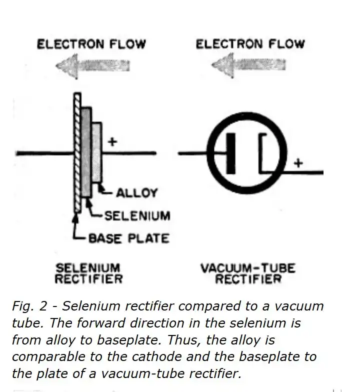
Selenium rectifiers do not use doped PN junctions like modern silicon or germanium diodes. Instead, they operate using a metal–semiconductor junction with a naturally formed barrier oxide layer. The result is a one-way conduction effect similar to a diode, but achieved through different means.
| Feature | Description |
|---|---|
| Voltage drop | ~1V per cell (higher than silicon or germanium) |
| Reverse leakage | Higher than modern PN diodes |
| Efficiency | Lower due to forward drop and heating |
| Durability | Very rugged; can withstand overloads |
| Recovery time | Slow (not suitable for high-frequency use) |
| Common Uses | Vintage TVs, battery chargers, early power supplies |
Selenium rectifiers are built from multiple thin metal–selenium cells stacked in series. This design is not just mechanical — it improves the electrical performance in several ways:
Many stacks also include cooling fins or air gaps between plates to improve heat dissipation during high-load operation.
Selenium rectifiers operate through a metal–semiconductor junction with a critical oxide layer (SeO₂), not by PN junctions. Though largely obsolete today, they played an essential role in early power electronics before being replaced by silicon diodes.
