
Exploring the unseen: A Crookes tube reveals the elegance of natural laws.
Larger Image | Visit Hobby Page
by Lewis Loflin
In 1977, while I was a high school student with a keen interest in electronics and inspired by early experimental physics, I built a functioning Crookes-style gas discharge tube. This project not only won the school science fair but also solidified my lifelong passion for applied science. I used salvaged high-voltage components from old televisions, an olive jar, and a vacuum pump to recreate a version of the classic cathode ray tube, similar to the one that guided J.J. Thomson in his discovery of the electron.
Off site:
See Crooks Tube Demo
See DIY Electron Accelerator: a Cathode Ray Tube in a Wine Bottle
See Crook"s Tube Pinwheel image.
My interest in the project originated from two main sources: my experience repairing televisions, which familiarized me with the workings of flyback transformers, cathode ray tubes (CRTs), and high-voltage rectification, and my readings on early atomic physics, particularly J.J. Thomson’s cathode ray experiments in the late 19th century. These experiments were crucial in advancing our understanding of subatomic particles, and I wanted to recreate that exploration through hands-on work.
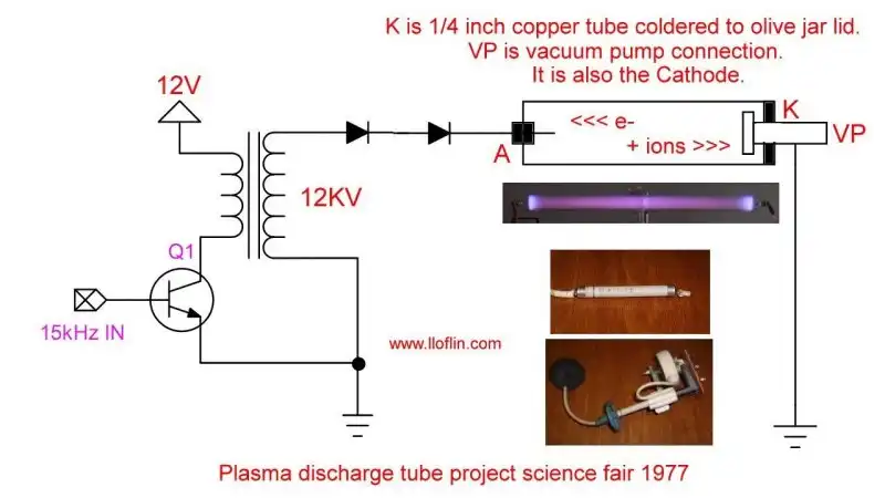
The core of the tube used a clear olive jar as the vacuum chamber. I drilled a small hole through the bottom of the glass jar using a diamond-tipped bit, then carefully sealed a metal wire into it with refrigeration-grade epoxy to serve as the anode. The jar’s metal lid served as the cathode, into which I drilled a larger hole and soldered a ¼-inch copper tube through it. At the end of this copper tube, I mounted a metal target electrode directly in the path of the ion beam. A small hole in the side of the copper tube allowed connection to a vacuum pump via tubing. The lid was sealed using vacuum grease, creating a serviceable vacuum chamber.
Once I removed most of the air, I applied 12,000 volts DC to the electrodes, using a flyback transformer driven by a 15.734 kHz oscillator and a step-up flyback transformer. A high-voltage TV rectifier rectified the high-voltage AC. (See illustration.) The result was a vivid glow discharge inside the jar — a visible plasma arc stretching from cathode to anode — its color and behavior varying depending on the residual gas inside.
What fascinated me most was not just the glow but the directional ion beam that formed. The visible streamer bombarded the cathode target. I used magnets around the jar to deflect this beam and observed how the plasma arc would bend or shift—a visible demonstration of charged particle motion in a magnetic field, much like the Lorentz force at work in a cyclotron. I experimented with different gases, including air, hydrogen, and argon, by adjusting the vacuum level and introducing small amounts of gas before sealing the system. Each gas produced different glow characteristics, intensities, and beam behaviors.
One of the most striking results was the physical damage to the cathode target. After extended operation, I noticed a pit had formed in the copper - clear evidence of ion bombardment. Positive ions from the gas, accelerated by the high-voltage field, slammed directly into the metal target and eroded it. This pitting was direct, physical proof of particle momentum transfer - the very mechanism behind early atomic beam experiments and a principle used today in ion etching and plasma physics.
At the time, I didn't realize how closely this project reflected the history of professional scientific endeavors. Only later did I appreciate that I had replicated - with 1970s garage tools — many of the core principles demonstrated by Crookes, Thomson, and others who laid the groundwork for modern atomic theory. I hadn't built a toy or science demo; I had built a legitimate plasma physics apparatus.
This project marked a turning point for me. It wasn't just about winning a science fair; it was about discovering the power of applied science - where experimentation, not speculation, reveals nature's secrets. It reinforced my belief that real science must be grounded in testable phenomena, not theoretical babble or academic consensus. It showed me that even with modest tools and salvaged parts, one can explore the fundamental workings of the universe - from electrons to ion beams - with curiosity, care, and a soldering iron.
See Overview Vacuum Tube TV and Radio Parts Schematics
Gas discharge tubes — like those found in neon lamps, fluorescent tubes, sodium vapor lamps, and xenon flash tubes — rely on low-pressure gas and high voltage to conduct electricity. When a high enough voltage is applied across a low-pressure gas, the gas becomes ionized and forms a conductive plasma.
In 1977, I built a homemade gas discharge tube for a science fair project using a vacuum pump, a sealed olive jar, and high-voltage TV parts. The tube was filled with low-pressure air, argon, or hydrogen. To energize it, I used a high-voltage, high-frequency AC or DC source.
Once the gas pressure was reduced and high voltage applied, the tube began to glow. The visible discharge showed where electrons were accelerated from the cathode (−) to the anode (+). In the process:
This experiment not only demonstrated plasma physics but also confirmed that in a vacuum, only electrons move, and they flow from negative to positive — not the other way around as in the "conventional current" model.
Other gas discharge systems behave similarly:
In all these tubes, ion bombardment damages the cathode over time. This is especially visible in fluorescent lamps, where the electrodes degrade, leading to blackening near the ends and eventual failure.
This is science in action — not simulation, but hands-on observation. A clear demonstration of electron flow, ionization, and real physical forces at work.
Standard NTSC horizontal frequency: 15.734 kHz
59.94 fields/sec × 262.5 lines/field = 15,734 lines/sec ≈ 15.734 kHzThis value is a stable and useful reference in many analog and digital video-related timing systems.
A flyback transformer is a special type of high-frequency transformer used to generate high-voltage pulses or isolated DC outputs. Originally developed for CRT televisions and monitors, it stores energy in the magnetic core and releases it rapidly, making it ideal for applications that require high-voltage, low-current outputs.
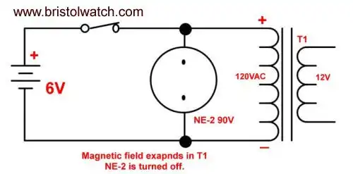
Fig. 5
In Fig. 5 we use a 6-volt battery and a power transformer used as an inductor. Power is supplied to the transformer primary though a switch and acts exactly as the inductor in Fig. 2 building up an intense magnetic field. Across the transformer winding is a NE-2 lamp that operates at 90 volts before it will begin to conduct. It stays off at 6-volts.
Also see Neon NE-2 Circuits You Can Build
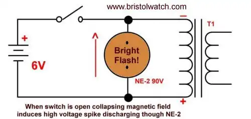
Fig. 6
In Fig. 6 when we open the switch instead of arching across the contracts the high voltage spike discharges though the NE-2 lamp producing a brief, intense purple-orange flash. Note once again the induced voltage polarity is opposite of the voltage that created it.
See my webpage Generating High Voltage with an Inductor.
Note: Flyback transformers generate high voltages that can be dangerous. Always use proper safety precautions when handling or experimenting with them.
See Flyback Transformer (25kV AC) for sale.
A typical 12-inch black-and-white CRT requires a high-voltage DC supply in the range of:
⚠️ Safety Note: Flyback circuits can store charge even after power-off. Always discharge safely before handling CRT circuitry.
A black-and-white cathode ray tube (CRT) uses a series of electrodes to generate, control, and accelerate an electron beam that strikes a phosphor-coated screen to produce visible light.
| Electrode | Function |
|---|---|
| 1. Cathode | Heated by a filament; emits electrons via thermionic emission |
| 2. Control Grid (G1) | Regulates brightness by controlling electron flow (typically −50 V to −100 V) |
| 3. Accelerating Anode (G2) | Pulls electrons forward with a positive voltage (~400 V to 600 V) |
| 4. Focus Electrode (G3) | Adjusts beam sharpness (~+100 V to +300 V, often variable) |
| 5. Final Anode (A) | Applies high voltage (~10–15 kV) to accelerate electrons toward the screen |
Note: The deflection of the beam (horizontal and vertical) is typically handled by external coils, not internal electrodes, in most B/W CRTs.
A damper diode is used in the horizontal deflection circuit of CRT televisions to:
The damper diode is connected across the collector-emitter (C-E) of the Horizontal Output Transistor (HOT). In later designs, the diode is often integrated into the HOT package itself.
Note: While related in function, the damper diode is not located in the flyback transformer and is distinct from the high-voltage rectifiers used for the CRT anode.
Adjusts the high voltage to the CRT’s focus electrode. This determines the sharpness of the electron beam and image clarity.
Sets the voltage on the screen grid (G2). Affects beam acceleration and total current. This has an indirect effect on brightness, but excessive G2 voltage may cause blooming or retrace lines.
Brightness is primarily set by:
These are separate from the flyback transformer circuit.
Note: The common labeling of “screen” as brightness is misleading. It is better understoo as part of beam acceleration and background illumination control.
This reference compares three common selenium HV rectifiers used in CRT televisions and high-voltage circuits. These devices are low-current, high-voltage rectifiers — not to be confused with silicon power diodes.
| Part Number | Reverse Voltage (VR) | Forward Current (IF) | Application | Notes |
|---|---|---|---|---|
| NTE504 | ~23,000 V | ~0.2 mA | Flyback HV rectifier | Replaces GECR-6, low-current selenium, epoxy case |
| GECR-6 | ~23,000 V | ~0.2 mA | Same as NTE504 | Compact axial-leaded selenium stack |
| ECG118 | ~6,500 V | ~0.5 mA | Focus rectifier | Used in CRT focus bias circuits |
Reminder: These are not high-current devices. Despite the high voltage, low current (under 2mA) for CRT anodes.
If you have photos or part packages to include, they make a great visual comparison of diode evolution.
In vintage CRT televisions, especially black-and-white models, selenium high-voltage rectifiers like the GECR-6 or NTE504 were common in flyback circuits. These rectifiers were adequate for the standard horizontal scan frequency of 15.75 kHz (NTSC), which remained consistent across generations of CRT sets.
Bottom line: The horizontal frequency didn’t change — but the speed and efficiency demands on HV rectifiers increased with the advent of fast-switching solid-state circuits, prompting the shift to silicon.

74C14 Schmitt trigger based pulse generator and switch debounce circuit.
Larger image |
Visit Hobby Page