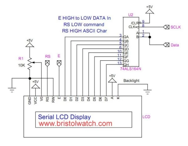
LCD display connected to 74LS164 shift register.
by Lewis Loflin
This project demonstrates how to interface a PIC16F57 microcontroller with a 16x2 character LCD using a serial connection through a 74ALS164 shift register, while also handling input from a 4×4 matrix keypad. The system uses only four I/O pins to control the LCD, freeing valuable I/O resources on the limited PIC16F57. Keypresses from the keypad are read in real-time and displayed on the LCD as ASCII characters. This example showcases efficient I/O usage, bit-level serial data handling, and practical embedded interfacing techniques suitable for small 8-bit microcontrollers.
| Function | PIC Output | Destination | Description |
|---|---|---|---|
| Serial Data | Data |
Pin 1 (A) – 74ALS164 | Shift register data input |
| Serial Clock | SCLK |
Pin 2 (B) – 74ALS164 | Clock input (rising edge) |
| RS | RS |
Pin 4 – LCD | LOW = command, HIGH = character |
| E (Enable) | E |
Pin 6 – LCD | Latch signal on falling edge |
Note: LCD D0–D7 connect to QA–QH of the 74ALS164 (in order).
Use shift + latch approach to send bytes serially: shift 8 bits → toggle E → done.
This project demonstrates interfacing a PIC16F57 with a serial LCD using a 74164 shift register and scanning a 4×4 matrix keypad. Key presses are immediately printed to the LCD as ASCII characters.
void main(void) {
    lcdInit();
    keypad_init();
    char key;
    while(1) {
        key = getKey();
        if (key) {
            writeByte(key, 1);  // Display character
        }
    }
}
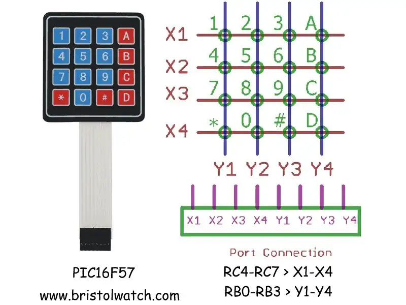
The keypad layout (hex 0-F with * and #):
 1  2  3  A
 4  5  6  B
 7  8  9  C
 *  0  #  D
Function: writeByte Description: Sends an 8-bit byte to an LCD using a shift register (e.g., 74ALS164). The data is clocked in one bit at a time on LCD_DATA, synchronized with LCD_CLK. The RS (Register Select) line is set based on the is_data flag to distinguish between command (0) and data (1) mode. After shifting in the byte, the LCD_E line is pulsed to latch the data into the LCD controller. Includes required timing delays for reliable operation.
void writeByte(unsigned char byte, unsigned char is_data) {
    LCD_RS = is_data & 0x01;
    for (char i = 0; i < 8; i++) {
        if (byte & 0x80)
            LCD_DATA = 1;
        else
            LCD_DATA = 0;
        LCD_CLK = 1;
        __delay_us(10);
        LCD_CLK = 0;
        __delay_us(10);
        byte <<= 1;
    }
    __delay_ms(2);
    // pulseE();
    LCD_E = 1;
    __delay_us(10);
    LCD_E = 0;
    __delay_us(50);
    LCD_DATA = 0;
    LCD_CLK = 0;
}
This function scans a 4×4 keypad connected to a PIC microcontroller. It works by:
key_map[row][col] lookup table.getKey():char getKey(void) {
char row, col;
for (row = 0; row < 4; row++) {
// Set RC4, RC5, RC6, RC7 (rows) all HIGH
PORTC = PORTC | 0b11110000;
// Set one row LOW at a time
PORTC = PORTC & ~(1 << (4 + row));
__delay_us(50); // Wait for signals to settle
// Now check the 4 column input pins RB0 to RB3
for (col = 0; col < 4; col++) {
// If a key is pressed, the column goes LOW
if ((PORTB & (1 << col)) == 0) {
// Wait for the key to be released
while ((PORTB & (1 << col)) == 0);
__delay_ms(10); // Debounce delay
return key_map[row][col]; // Return corresponding key
}
}
}
return 0; // No key pressed
}PORTC | 0b11110000: Set all rows HIGH.~(1 << (4 + row)): Clear one row (set it LOW).PORTB & (1 << col): Check if a column is LOW (key press).💡 You can display the returned character on an LCD or send it over serial to verify key input.
| Keypad Line | PIC16F57 Pin | Port Bit | Direction | Notes |
|---|---|---|---|---|
| X1 (Row 1) | 23 | RC4 | Output | Drive LOW to scan |
| X2 (Row 2) | 24 | RC5 | Output | |
| X3 (Row 3) | 25 | RC6 | Output | |
| X4 (Row 4) | 26 | RC7 | Output | |
| Y1 (Col 1) | 10 | RB0 | Input | 10 kΩ pull-up to +5V |
| Y2 (Col 2) | 11 | RB1 | Input | 10 kΩ pull-up to +5V |
| Y3 (Col 3) | 12 | RB2 | Input | 10 kΩ pull-up to +5V |
| Y4 (Col 4) | 13 | RB3 | Input | 10 kΩ pull-up to +5V |
Scan Method: Set all row outputs HIGH, then set one LOW at a time. Read the column inputs (active LOW) to detect key presses.
Debounce: After detecting a key press, wait for release and add ~10 ms delay.
Below is a C program for interfacing a 4x4 keypad and an LCD display with a PIC microcontroller. The code configures the microcontroller, initializes the keypad and LCD, and displays pressed keys on the LCD. It includes configuration bits, pin definitions, and functions for keypad scanning and LCD communication.
#include <xc.h>

// Configuration bits
#pragma config WDT = OFF   // Watchdog Timer disabled
#pragma config CP = OFF     // Code protection off
#pragma config OSC = XT     // XT Oscillator (use 4 MHz crystal)

#define _XTAL_FREQ 4000000UL

#define LCD_E  RA0 // blue
#define LCD_RS RA1 // green
#define LCD_DATA RA2 // orange
#define LCD_CLK  RA3 // yellow

#define MSG1 "Hello World!"
#define LINE0 0x80
#define LINE1 0xC0

const char key_map[4][4] = {
    {'1', '2', '3', 'A'},
    {'4', '5', '6', 'B'},
    {'7', '8', '9', 'C'},
    {'*', '0', '#', 'D'}
};

// Set columns (RC4-RC7) high initially
void keypad_init(void) {
    TRISB = 0x0F;  // RB0-RB3 inputs (rows)
    TRISC = 0x0F;  // RC4-RC7 outputs (columns)
    PORTC |= 0xF0; // Ensure RC4-RC7 are high (inactive)
}

char getKey(void) {
    for (char row = 0; row < 4; row++) {
        // Set all RC4-RC7 high
        PORTC |= 0xF0;
        // Drive one row low at a time (RC4 = bit 4)
        PORTC &= ~(1 << (4 + row));
        __delay_us(50);  // Allow lines to settle

        // Check each column input (RB0-RB3)
        for (char col = 0; col < 4; col++) {
            if (!(PORTB & (1 << col))) {  // If key is pressed (active low)
                while (!(PORTB & (1 << col)));  // Wait for release (blocking)
                __delay_ms(10);  // Basic debounce
                return key_map[row][col];
            }
        }
    }
    return 0;  // No key pressed
}

void writeByte(unsigned char byte, unsigned char is_data) {
    LCD_RS = is_data & 0x01;
    for (char i = 0; i < 8; i++) {
        if (byte & 0x80)
            LCD_DATA = 1;
        else
            LCD_DATA = 0;
        LCD_CLK = 1;
        __delay_us(10);
        LCD_CLK = 0;
        __delay_us(10);
        byte <<= 1;
    }
    __delay_ms(2);
    // pulseE();
    LCD_E = 1;
    __delay_us(10);
    LCD_E = 0;
    __delay_us(50);
    LCD_DATA = 0;
    LCD_CLK = 0;
}

void lcdInit(void) {
    // Clear output ports
    PORTA = 0x00;
    PORTB = 0x00;
    PORTC = 0x00;
    // TRIS settings
    TRISA = 0x00; // Lower 4 bits output
    TRISB = 0xFF; // All input
    TRISC = 0xFF; // All input
    // lcd_init();
    LCD_E = 0;
    LCD_RS = 0;
    LCD_DATA = 0;
    LCD_CLK = 0;

    __delay_ms(20);
    writeByte(0x38, 0);
    writeByte(0x0C, 0);
    writeByte(0x06, 0);
    writeByte(0x01, 0);
    __delay_ms(2);
}

void lcd_print(const char *str) {
    while (*str) {
        writeByte(*str++, 1);
    }
}

void main(void) {

    lcdInit();
    keypad_init();
    writeByte(0x80, 0); // top line
    lcdPrint(MSG1);
    writeByte(0xC0, 0); // 2nd line
    char key;
    //writeByte('H', 1); // test display

    while(1) {
    key = getKey();
    if (key) {
        writeByte(key, 1);  // print character to LCD
    // __delay_ms(20);
    }
}
     // lcd_print("Hello World!");

}
This example shows how the minimal-stack PIC16F57 can be used for practical embedded tasks with efficient code and basic peripherals. By using serial shift and port scanning, it effectively manages a keypad and LCD with just 12 I/O lines. (8 for keypad, 4 for LCD display.)

