by Lewis Loflin
What Are Interrupts?
Interrupts are special signals that temporarily divert the microcontroller from its main program to respond to urgent events like input changes or timer overflows. When an interrupt occurs, the microcontroller temporarily halts its main execution flow and jumps to a separate routine called the Interrupt Service Routine (ISR). Once the ISR completes, normal program flow resumes from where the interrupt occurred. This allows the microcontroller to react instantly to time-sensitive inputs without constantly polling them in software.
How the Hardware Stack Works
The PIC16F84A has a limited hardware stack that stores the return address when executing a subroutine (CALL) or servicing an interrupt. This stack has only 8 levels, which means it can remember up to 8 nested return addresses. When an interrupt occurs, the current program counter (PC) is pushed onto the stack, then the CPU jumps to address 0x0004 to execute the ISR. When the ISR finishes (via RETFIE), the return address is popped off the stack, and execution resumes where it left off.
Subroutines also use the stack. Each CALL instruction pushes the return address so that a RETURN can resume execution. However, if the stack overflows (e.g., too many nested CALLs or an interrupt occurs during deep nesting), the return address will be lost or overwritten — leading to unpredictable behavior. Because of this, the limited stack size in the PIC16F84A demands careful design when using both subroutines and interrupts.
These interrupts allow responsive designs such as keypad edge detection, frequency counting, timed tasks, or external event handling. All of this builds on the foundation already established with the TMR0-based binary counter and LCD display.
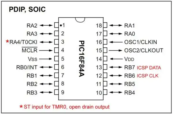
When configured as an interrupt, RB0 has a Schmitt Trigger input; otherwise, it behaves as a TTL-level input. PORTB also features internal weak pull-ups when OPTION_REGbits.RBPU = 0. Inputs RB4–RB7 can trigger interrupts on any logic level change. (See PIC16F84A datasheet, page 11.)
Example Application:
Use the INT (RB0) pin to receive a 60Hz signal. The ISR counts pulses and toggles RA2 every 30 interrupts to produce a 1Hz square wave. For a 120Hz zero-crossing circuit, toggle every 60 interrupts.
On the PIC16F84A, the interrupt system is not nested, meaning that only one interrupt can be serviced at a time. When an interrupt occurs, the global interrupt enable bit (GIE) in the INTCON register is automatically cleared by hardware. This disables all further maskable interrupts while the ISR is running.
What does this mean?
RB0/INT interrupt is being serviced, no other interrupt — including TMR0 overflow or RB4–RB7 change — can trigger until the ISR exits and GIE is re-enabled via RETFIE.Example Scenario:
If RB0 is triggered and enters its ISR, but during execution a state change happens on RB4, the microcontroller will not recognize the RB4–RB7 change interrupt at that time. After RETFIE completes and GIE is restored, the interrupt-on-change condition may no longer be valid, and the event will be missed.
Because of this, interrupt service routines should be kept as short and efficient as possible. Do not use __delay_ms() or long loops inside an ISR, as these delay re-enabling GIE and risk missing additional interrupts.
#include <xc.h>

// CONFIGURATION
#pragma config FOSC = XT
#pragma config WDTE = OFF
#pragma config PWRTE = ON
#pragma config CP = OFF

#define _XTAL_FREQ 4000000UL

volatile unsigned char count = 0;
// Interrupt counter (must be volatile since modified in ISR)


// Interrupt Service Routine
void __interrupt() isr(void) {
    if (INTCONbits.INTF) {         // RB0 interrupt occurred
        count++;                   // Increment on each 60Hz pulse
        if (count >= 30) { // 500mS with 60Hz input
            PORTBbits.RB1 ^= 1;    // Toggle RB1 twice to create 1Hz output
            count = 0;             // Reset counter
        }
        INTCONbits.INTF = 0;   // Clear interrupt flag (must be done manually)
    }
}

void main(void) {
    TRISBbits.TRISB0 = 1;  // RB0/INT as input

    TRISBbits.TRISB1 = 0;  // RB1 as output (LED or signal)
    PORTBbits.RB1 = 0;     // Start low

    OPTION_REGbits.INTEDG = 0;  // Trigger on falling edge
    INTCONbits.INTE = 1;        // Enable RB0 external interrupt
    INTCONbits.GIE = 1;         // Enable global interrupts

    while (1) {
        // Main loop remains free — all timing is handled in ISR
    }
}
Notes:
INTEDG if rising is neededThis program uses PORTB interrupt-on-change to toggle LEDs on RB1–RB3 when corresponding switches on RB4–RB6 are pressed. Each switch is pulled low through a 120Ω resistor. Internal pull-ups are enabled.
#include <xc.h>

// CONFIGURATION BITS
#pragma config FOSC = XT
#pragma config WDTE = OFF
#pragma config PWRTE = ON
#pragma config CP = OFF

#define _XTAL_FREQ 4000000UL


volatile unsigned char last_state = 0xFF;

void __interrupt() isr(void) {
    if (INTCONbits.RBIF) {

        __delay_ms(20);        // Debounce all inputs (global delay)

        unsigned char current = PORTB;
        unsigned char change = current ^ last_state;

        // Check RB4 → Toggle RB1
        if (!PORTBbits.RB4) {
            while (!PORTBbits.RB4);    // Wait for release
            PORTBbits.RB1 ^= 1;
        }

        // Check RB5 → Toggle RB2
        if (!PORTBbits.RB5) {
            while (!PORTBbits.RB5);    // Wait for release
            PORTBbits.RB2 ^= 1;
        }

        // Check RB6 → Toggle RB3
        if (!PORTBbits.RB6) {
            while (!PORTBbits.RB6);    // Wait for release
            PORTBbits.RB3 ^= 1;
        }

        last_state = current;          // Update stored state
        INTCONbits.RBIF = 0;           // Clear interrupt flag
    }
}


void main(void) {
    TRISB = 0b11110001;  // RB0 input (INT), RB4–RB7 inputs, RB1–RB3 outputs
    PORTB = 0x00;        // Clear outputs
    OPTION_REGbits.nRBPU = 0;  // Enable PORTB pull-ups
    last_state = PORTB;        // Read initial state

    INTCONbits.RBIE = 1;  // Enable RB4–RB7 interrupt-on-change
    INTCONbits.GIE = 1;   // Enable global interrupts

    while (1) {
        // Main loop does nothing; waiting for interrupts
    }
}
nRBPU = 0 (active low bit).// Check RB4 → Toggle RB1
if (!PORTBbits.RB4) {
while (!PORTBbits.RB4); // Wait for release
PORTBbits.RB1 ^= 1; // Toggle LED on RB1
}if (!PORTBbits.RB4): Checks if the button connected to RB4 is pressed. Since it's assumed to be active-low, a logical 0 means the button is down.while (!PORTBbits.RB4);: This loop waits until the button is released (RB4 goes back high). This serves as a basic debounce, filtering out bounce during release.PORTBbits.RB1 ^= 1;: Uses bitwise XOR to toggle the state of RB1. If it was ON, it turns OFF; if it was OFF, it turns ON.You can add a small __delay_ms(20) after the initial press check for better bounce suppression:
if (!PORTBbits.RB4) {
    __delay_ms(20);              // debounce delay
    while (!PORTBbits.RB4);      // wait for release
    PORTBbits.RB1 ^= 1;
}The INTCON register is a readable and writable control register that manages interrupts on the PIC16F84A. It holds the individual enable and flag bits for all interrupt sources.
Use this register to globally enable or disable interrupts and to check if specific interrupt events have occurred.
| Bit | Name | Description |
|---|---|---|
| 7 | GIE Global Interrupt Enable |
1 = Enables all unmasked interrupts 0 = Disables all interrupts |
| 6 | EEIE EE Write Complete Interrupt Enable |
1 = Enables the EE Write Complete interrupts 0 = Disables the EE Write Complete interrupt |
| 5 | T0IE TMR0 Overflow Interrupt Enable |
1 = Enables the TMR0 interrupt 0 = Disables the TMR0 interrupt |
| 4 | INTE RB0/INT External Interrupt Enable |
1 = Enables the RB0/INT external interrupt 0 = Disables the RB0/INT external interrupt |
| 3 | RBIE RB Port Change Interrupt Enable |
1 = Enables the RB port change interrupt 0 = Disables the RB port change interrupt |
| 2 | T0IF TMR0 Overflow Interrupt Flag |
1 = TMR0 register has overflowed (must be cleared in software) 0 = TMR0 register did not overflow |
| 1 | INTF RB0/INT External Interrupt Flag |
1 = The RB0/INT external interrupt occurred (must be cleared in software) 0 = The RB0/INT external interrupt did not occur |
| 0 | RBIF RB Port Change Interrupt Flag |
1 = At least one of the RB7:RB4 pins changed state (must be cleared in software) 0 = None of the RB7:RB4 pins have changed state |
The OPTION register is both readable and writable. It controls several important features of the PIC16F84A microcontroller, including:
TMR0 or the Watchdog Timer (WDT)RB0/INT pin
Proper configuration of this register is essential for controlling timer behavior, managing external interrupts, and setting logic states on PORTB.
| Bit | Name | Description | |||||||||||||||||||||||||||
|---|---|---|---|---|---|---|---|---|---|---|---|---|---|---|---|---|---|---|---|---|---|---|---|---|---|---|---|---|---|
| 7 | RBPU PORTB Pull-up Enable |
1 = PORTB pull-ups are disabled 0 = PORTB pull-ups are enabled by individual port latch values |
|||||||||||||||||||||||||||
| 6 | INTEDG Interrupt Edge Select |
1 = Interrupt on rising edge of RB0/INT pin 0 = Interrupt on falling edge of RB0/INT pin |
|||||||||||||||||||||||||||
| 5 | T0CS TMR0 Clock Source Select |
1 = Transition on RA4/T0CKI pin 0 = Internal instruction cycle clock (CLKOUT) |
|||||||||||||||||||||||||||
| 4 | T0SE TMR0 Source Edge Select |
1 = Increment on high-to-low transition on RA4/T0CKI pin 0 = Increment on low-to-high transition on RA4/T0CKI pin |
|||||||||||||||||||||||||||
| 3 | PSA Prescaler Assignment |
1 = Prescaler is assigned to the Watchdog Timer (WDT) 0 = Prescaler is assigned to the Timer0 module |
|||||||||||||||||||||||||||
| 2–0 | PS2:PS0 Prescaler Rate Select |
|
