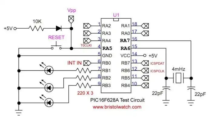
No Crystal with Switches Schematic | Visit Hobby Page

The following example demonstrates how to use the PIC16F628A to generate a stable 1Hz square wave output on RB1 by counting 60Hz pulses from an external source connected to RB0. This method uses an interrupt service routine (ISR) to maintain precise timing while leaving the main loop free for other tasks. With minimal code and no reliance on polling or timers, this technique is ideal for time-critical embedded systems using mains-derived frequency sources.
Function: Use the INT (RB0) pin to receive a 60Hz signal. The ISR counts pulses and toggles RB1 every 30 interrupts to produce a 1Hz square wave.
#include <xc.h>

// CONFIGURATION
#pragma config FOSC = XT
#pragma config WDTE = OFF
#pragma config PWRTE = ON
#pragma config MCLRE = OFF
#pragma config BOREN = OFF
#pragma config LVP = OFF
#pragma config CPD = OFF
#pragma config CP = OFF

#define _XTAL_FREQ 4000000

volatile unsigned char count = 0;  // Interrupt counter

// Interrupt Service Routine
void __interrupt() isr(void) {
    if (INTCONbits.INTF) {         // RB0 interrupt occurred
        count++;                   // Increment on each 60Hz pulse
        if (count >= 30) {
            PORTBbits.RB1 ^= 1;    // Toggle RB1 to create 1Hz output
            count = 0;             // Reset counter
        }
        INTCONbits.INTF = 0;       // Clear interrupt flag
    }
}

void main(void) {
    TRISBbits.TRISB0 = 1;  // RB0/INT as input
    TRISBbits.TRISB1 = 0;  // RB1 as output (LED or signal)
    PORTBbits.RB1 = 0;     // Start low

    OPTION_REGbits.INTEDG = 0;  // Trigger on falling edge
    INTCONbits.INTE = 1;        // Enable RB0 external interrupt
    INTCONbits.GIE = 1;         // Enable global interrupts

    while (1) {
        // Main loop remains free — all timing is handled in ISR
    }
}
Notes:
INTEDG if rising is needed
Optocoupler AC zero crossing detector output 120Hz.
Larger image |
Visit Hobby Page
Variable-Frequency Oscillator Using 74C14 / 74HC14
MCLRE = OFF turns RA5 into a digital I/O pin; disables external reset.