
by Lewis Loflin
Note: while the above uses the PIC16F57 the LCD code is identical.
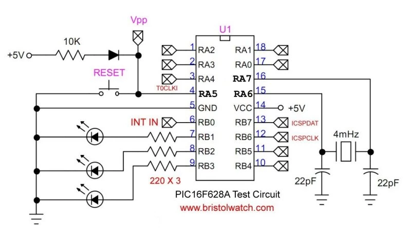
This project demonstrates how to display a 16-bit binary number in decimal format on a standard HD44780-compatible LCD using the PIC16F628A microcontroller. Building on the earlier "Hello World!" LCD example, this version introduces binary-to-decimal conversion with leading zero suppression and a modular 4-bit LCD interface. The setup efficiently uses just six I/O pins and provides a foundation for real-world applications such as voltmeters, counters, and sensor readouts. Though demonstrated on the PIC16F628A, the code is compatible with the PIC16F57 and similar devices.
This demo builds on the earlier "Hello World!" LCD example by adding real number processing. It converts a 16-bit binary value to a human-readable decimal string and displays it using a 4-bit interface LCD. This showcases several important microcontroller programming concepts in C.
Instead of just printing fixed strings, the program now processes a 16-bit unsigned int and converts it to a 5-digit ASCII decimal number for display:
void to_decimal_ascii(unsigned int value, char buf[5]) {
    buf[0] = (value / 10000) % 10 + '0';
    buf[1] = (value / 1000) % 10 + '0';
    buf[2] = (value / 100) % 10 + '0';
    buf[3] = (value / 10) % 10 + '0';
    buf[4] = (value % 10) + '0';
}
This is a clean and readable way to extract each decimal digit from a binary value using division and modulus.
The function lcd_print_trimmed() is used to skip over leading zeros, which would otherwise clutter the display. This makes the number easier to read:
void lcd_print_trimmed(const char *buf, unsigned char len) {
    unsigned char i = 0;
    while (i < len - 1 && buf[i] == '0') i++;
    while (i < len) {
        lcd_send_byte(buf[i++], 1);
    }
}The LCD functions are cleanly organized:
lcd_init() - Initializes the LCDlcd_send_byte() - Sends full commands or characterslcd_nibble() - Sends 4-bit chunkslcd_print() - Prints stringslcd_print_trimmed() - Prints digit strings without leading zerosThis modular approach makes it easy to reuse code across future projects.
The LCD is driven in 4-bit mode, using only six pins total (RA0, RA1, and RB0-RB3). This leaves more pins available for sensors, buttons, or other peripherals - a necessity for small devices like the PIC16F628A.
This example now forms the basis for practical applications like:
It bridges the gap between beginner-level string printing and real data display from hardware.
This example demonstrates using the PIC16F628A to:
FOSC = INTOSCIO)The LCD functions are cleanly organized:
lcd_init() - Initializes the LCDlcd_send_byte() - Sends full commands or characterslcd_nibble() - Sends 4-bit chunkslcd_print() - Prints string literalslcd_print_trimmed() - Skips leading '0's in numbers#include <xc.h>
#pragma config FOSC = XT // use 4 mHz crystal
#pragma config WDTE = OFF
#pragma config PWRTE = ON
#pragma config MCLRE = ON
#pragma config BOREN = OFF
#pragma config LVP = OFF
#pragma config CPD = OFF
#pragma config CP = OFF
#define _XTAL_FREQ 4000000
#define LCD_RS RA1
#define LCD_E RA0
#define LCD_D4 RB0
#define LCD_D5 RB1
#define LCD_D6 RB2
#define LCD_D7 RB3
void pulse_enable() {
LCD_E = 1;
__delay_us(1);
LCD_E = 0;
__delay_us(50);
}
void lcd_nibble(unsigned char nibble) {
LCD_D4 = (nibble >> 0) & 1;
LCD_D5 = (nibble >> 1) & 1;
LCD_D6 = (nibble >> 2) & 1;
LCD_D7 = (nibble >> 3) & 1;
pulse_enable();
}
void lcd_send_byte(unsigned char byte, unsigned char is_data) {
LCD_RS = is_data;
lcd_nibble(byte >> 4); // High nibble
lcd_nibble(byte & 0x0F); // Low nibble
__delay_ms(2);
}
void lcd_init() {
TRISAbits.TRISA0 = 0;
TRISAbits.TRISA1 = 0;
TRISB &= 0xF0;
__delay_ms(20);
LCD_RS = 0;
lcd_nibble(0x03); __delay_ms(5);
lcd_nibble(0x03); __delay_us(150);
lcd_nibble(0x03);
lcd_nibble(0x02); // 4-bit mode
lcd_send_byte(0x28, 0); // 2 lines, 5x8 font
lcd_send_byte(0x0C, 0); // Display ON
lcd_send_byte(0x06, 0); // Entry mode
lcd_send_byte(0x01, 0); // Clear
__delay_ms(2);
}
void lcd_print(const char *str) {
while (*str) {
lcd_send_byte(*str++, 1);
}
}
// Converts 16-bit unsigned int to 5-digit ASCII in buf[]
void to_decimal_ascii(unsigned int value, char buf[5]) {
buf[0] = (value / 10000) % 10 + '0';
buf[1] = (value / 1000) % 10 + '0';
buf[2] = (value / 100) % 10 + '0';
buf[3] = (value / 10) % 10 + '0';
buf[4] = (value % 10) + '0';
}
void lcd_print_trimmed(const char *buf, unsigned char len) {
unsigned char i = 0;
while (i < len - 1 && buf[i] == '0') i++;
while (i < len) {
lcd_send_byte(buf[i++], 1);
}
}
void main() {
CMCON = 0x07; // comparators off
lcd_init();
lcd_print("Hello!"); // Line 1
__delay_ms(1000);
lcd_send_byte(0xC0, 0); // Line 2
unsigned int value = 0xFF; // decimal 255
char bcd_ascii[6]; // 5 digits + null
to_decimal_ascii(value, bcd_ascii);
bcd_ascii[5] = '\0'; // safety null
lcd_print_trimmed(bcd_ascii, 5);
while (1) { /* idle */ }
}
This is more than just an upgrade to "Hello World!" - it's a working microcontroller display system with value conversion, display formatting, and modular design. It demonstrates how to get real numeric data onto a limited-resource LCD using clean and efficient C code.
MCLRE = OFF turns RA5 into a digital I/O pin; disables external reset.