How a Voltage Doubler Operates
by Lewis Loflin
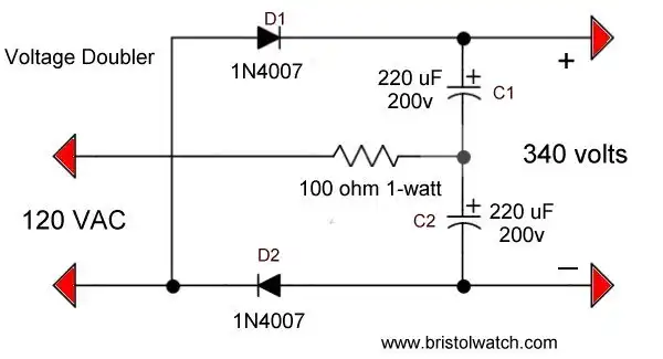
A voltage doubler circuit is used to produce a higher voltage direct current from a lower voltage alternating current. In its most basic form it consists of four components and is easy to build.
How it works. In the schematic above, capacitor C1 is charged through D1 every positive half-cycle. The voltage across C1 is the AC input voltage times 1.414 or about 170 volts in the case of 120 VAC input.
C2 is charged through D2 every negative half-cycle to 170 volts. The two charged capacitors are in series and the voltages add. The final voltage is 340 volts.
This will work with any AC input as long as the diodes and capacitors are the correct ratings. The 100 ohm resistor is used to limit the current surge if one uses very large capacitors and acts as a fuse. The part value is not critical.
An AC transformer secondary can also be connected as the input. I used a 25.2 volt unit to test diacs. See my Testing Diacs page.
Be very careful of high voltage shock hazards some of these circuits can produce.
YouTube Video Voltage Doubler Operation.
![]()
- Quick navigation of this website:
- You Tube Channel
- Basic Electronics Learning and Projects
- Basic Solid State Component Projects
- Arduino Microcontroller Projects
- Raspberry Pi Electronics, Programming
- Build Autotransformer-Variac AC and DC Power Supply
- Connecting Transformers in Series-Parallel
- Build an Adjustable 0-34 volt power supply with the LM317
- AC Power Supply Rectification
- Basic Power Transformers
- Transistor-Zener Diode Regulator Circuits
- Tips for the LM78XX Series Voltage Regulators
- Bi-Polar Power Supplies
- Connecting Series-Parallel Batteries
- ULN2003A Darlington Transistor Array with Circuit Examples
- Tutorial Using TIP120 and TIP125 Power Darlington Transistors
- Driving 2N3055-MJ2955 Darlington Transistors
- Understanding Bipolar Transistor Switches
- N-Channel Power MOSFET Switching Tutorial
- P-Channel Power MOSFET Switch Tutorial
- H-Bridge Motor Control with Power MOSFETs
- Arduino Controlled IR2110 Based H-Bridge HV Motor Control
- IGBT Based High Voltage H-Bridge DC Motor Control
- More Power MOSFET H-Bridge Circuit Examples
- Build a High Power Transistor H-Bridge Motor Control
- Basic Triacs and SCRs
- Constant Current Circuits with the LM334
- LM334 CCS Circuits with Thermistors, Photocells
- LM317 Constant Current Source Circuits
- TA8050P H-Bridge Motor Control
- All NPN Transistor H-Bridge Motor Control
- Basic Triacs and SCRs
- Comparator Theory Circuits Tutorial
Web site Copyright Lewis Loflin, All rights reserved.
If using this material on another site, please provide a link back to my site.