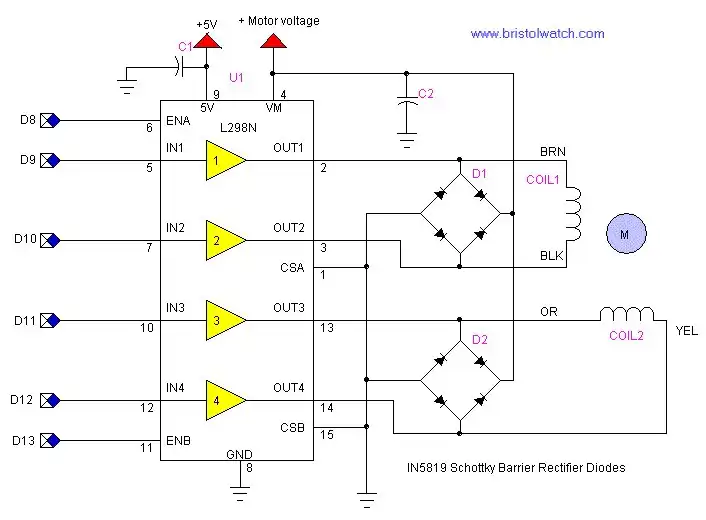
Figure 1 L298N Dual H-Bridge connected to a bi-polar stepper motor.
Interface Arduino Controlling L298N H-Bridge Motor Control
Earlier we looked at L298N Motor Controller Theory and Projects to understand the basic operation of the L298N dual H-bridge motor controller. In this section I've connected the L298N to a bi-polar stepper motor and connected it to the Arduino micro-controller. Note the motor voltage is the voltage rating of the stepper motor up to 40 volts and a current limit of four amps.
Note the motor voltage will have to doubled. For example if a unipolar motor is rated at 5-volts then in the bipolar mode will be 10-volts. This is due to the coils being operated in series.
The Arduino series of micro-controllers are an outstanding value for the hobbyist and student to learn the basics of programming and interfacing micro-controllers. In this example in both hardware and programming the code below will operate the stepper motor through the L298N.
The steppers I used in the example are all 7.5 degrees per-step and require 48 steps to go 360 degrees. Stepper motors are very accurate and often don't need feedback to tell position.
A bi-polar stepper motor has only two coils and operates by reversing the polarity unlike a unipolar stepper motor that operates by switching four coils on/off.
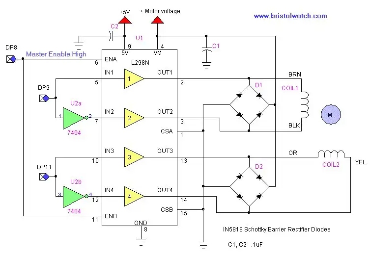
Figure 2
Here we have used only three connections to the Arduino micro-controller to operate the stepper motor. We tied ENA and ENB together and used two inverters from a 74LS04. We could still leave ENA and ENB separate if one wishes. In the program below simply remove any statements relating to ENB, yellow, or black which will free up three digital pins. It would also be a good idea change "#define orange 11" to #define orange 10" then wire digital pin 10 to IN3.
Download the Arduino code l298n_arduino.txt copy and past to the Arduino compiler.

Figure 3
Shown above is a pre-assembled board I bought off Ebay for $8 with shipping. This included power connectors, diodes, LED indicators, and even a 5-volt regulator. This is in my opinion the smart way to go to save time, money, and effort.
- H-Bridge Motor Control with Power MOSFETS Updated
- All NPN Transistor H-Bridge Motor Control
- IGBT Based High Voltage H-Bridge DC Motor Control
- Arduino Controlled IR2110 Based H-Bridge HV Motor Control
- Tri-State H-Bridge using CD4093B CMOS Circuit
- CMOS-MOSFET H-Bridge Circuit
- Interfacing Arduino to CMOS and MOSFET Circuits
- Quick navigation of this website:
- Basic Electronics Learning and Projects
- Basic Solid State Component Projects
- Arduino Microcontroller Projects
- Raspberry Pi Electronics, Programming
- Opto-Isolated transistor driver circuits.
- Transistor Driver Circuits
- Opto-Isolated Transistor Drivers
- Optical Isolation of H-Bridge Motor Controls
- MOSFET Transistors, IGBTs Observations
- Example H-Bridge Circuits
- L298N Motor Controller Theory and Projects
- Connecting the Arduino to a L298N H-Bridge
- All NPN Transistor H-Bridge Motor Control
- IGBT Based High Voltage H-Bridge DC Motor Control
- Arduino Controlled IR2110 Based H-Bridge HV Motor Control
- Tri-State H-Bridge using CD4093B CMOS Circuit
- CMOS-MOSFET H-Bridge Circuit
- Interfacing Arduino to CMOS and MOSFET Circuits
- Transistor circuits:
- ULN2003A Darlington Transistor Array with Circuit Examples
- Tutorial Using TIP120 and TIP125 Power Darlington Transistors
- Driving 2N3055-MJ2955 Power Transistors
- Understanding Bipolar Transistor Switches
- N-Channel Power MOSFET Switching Tutorial
- P-Channel Power MOSFET Switch Tutorial
- More Power MOSFET H-Bridge Circuit Examples
- Build a High Power Transistor H-Bridge Motor Control
- MOSFET-Transistor Drivers with TC4420 and TC4429, IGBTs, etc.
- Introduction TC4420-TC4429 MOSFET Drivers
- Use TC4420 MOSFET Driver for Simple H-Bridge Circuit
- TC4420 MOSFET Driver Various Circuits
- TC4420 MOSFET Driver Replacement Circuits
- Test Power MOSFET Transistors, IGBTs
- Insulated Gate Bipolar Transistor IGBT Circuits
- Issues on Connecting MOSFETs in Parallel
Stepper Motors
- Easy Driver Micro-Stepper Controller to Arduino
- Unipolar Stepper Motor with a Arduino
- MC3479 Stepper Motor Controller with Arduino
- Considerations for Using Stepper Motors
- Connecting the Arduino to a L298N H-Bridge
- L298N Motor Controller Theory and Projects
- TA8050 H-Bridge Motor Controller
- Arduino Stepper Motor Coil Winder
- Using Hall Effect Switches and Sensors
- ULN2003A Darlington Transistor Array with Circuit Examples
- Tutorial Using TIP120 and TIP125 Power Darlington Transistors
- H-Bridge Motor Control with Power MOSFETs
- More Power MOSFET H-Bridge Circuit Examples
- Build a High Power Transistor H-Bridge Motor Control
Web site Copyright Lewis Loflin, All rights reserved.
If using this material on another site, please provide a link back to my site.