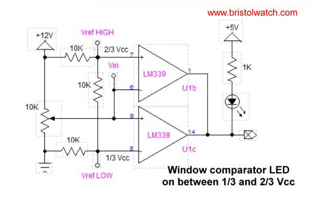
Fig. 1 Window Comparator using LM339
click picture for full size.
Looking at Window Comparator Circuits
by Lewis Loflin
A window comparator will output a voltage between two selected voltage points and be off outside that range. In Fig. 1 we have used 2 of 4 comparators in a LM339. The outputs of the each comparator in the LM339 is a open collector transistors tied together and connected to a LED and resistor. This open collector arrangement allows one to use a separate power supply form the rest of the circuit.
Note that U1b is connected as an inverting comparator while U1c is connected as a non-inverting comparator.
See Voltage Comparator Circuits
The rule for open collector comparator is both comparators must be turned OFF at the same time to output a HIGH. in Fig. 1 we use three 10,000 ohm resistors in series that produces 2/3s Vcc at Vref HIGH and 1/3 Vcc at Vref LOW.
On an inverting comparator if the MINUS input is greater than the PLUS input the internal open collector transistor is turned on. On a non-inverting comparator if the PLUS input is greater than the MINUS input the internal open collector transistor is turn on.
Thus the LED in Fig. 1 is on between these two voltages of 4V and 8V.
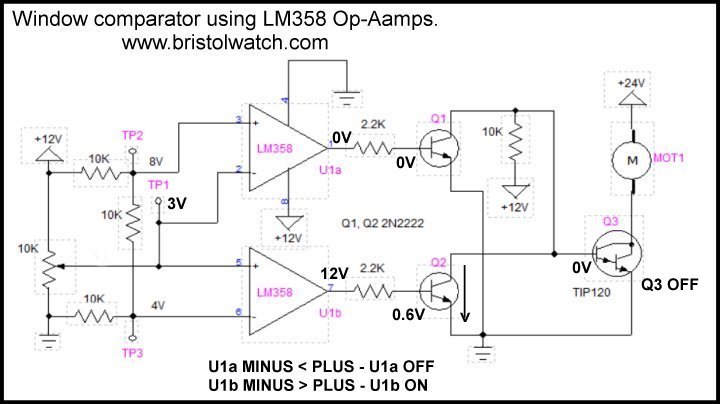
Fig. 2 Window comparator using LM358 dual Op-Amp at 3 volts.
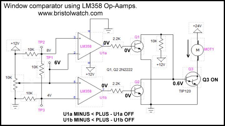
Fig. 3 Window comparator using LM358 dual Op-Amp at 6 volts.
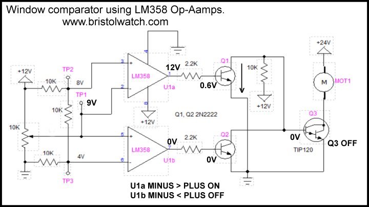
Fig. 4 Window comparator using LM358 dual Op-Amp at 9 volts.
Because each LM339 comparator is nothing more than an operational amplifier we can use a LM358 and do the same thing as Fig. 1 other than the output is 12-volts fed into two transistors Q1 and Q2. We use both a non-inverting and inverting comparators together. Vin is TP1.
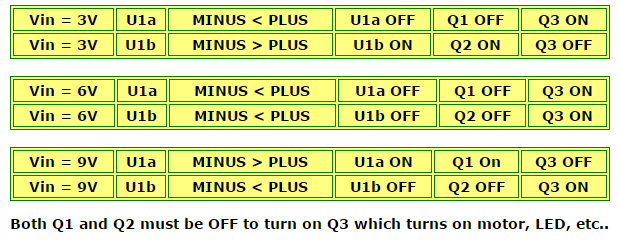
Above is the logic table for the window comparator circuit at different voltages at Vin. Output transistor Q3 is turned on by the 10K pull up resistor when both Q1 and Q2 are turned off at the same time.
![]()
- Quick navigation of this website:
- You Tube Channel
- Basic Electronics Learning and Projects
- Basic Solid State Component Projects
- Arduino Microcontroller Projects
- Raspberry Pi Electronics, Programming
A Hall sensor in its most basic form is an analog integrated circuit. It consists of a Hall plate that outputs a "transverse" voltage based on the intensity of a magnetic field - polarity is dependant on magnetic polarity.
It also consists of a high gain differential amplifier because the generated voltage is small. The output voltage is analog usually centered around half the power supply voltage.
The addition of a Schmitt trigger with a properly set hysteresis will create a Hall switch or Hall latch. They often have an open collector output transistor.
The Schmitt triggers used here are based on an analog comparator. These can be built from operational amplifiers (op-amps) like the LM358 or LM741.
Or one can use the LM311 or LM339 quad comparator. The have open collector outputs unlike the LM311/LM741.
Often considered "digital" at this point we have in reality a one-bit analog-to-digital converter.
- Comparator Theory Circuits Tutorial
- Comparator Hysteresis and Schmitt Triggers
- Voltage Comparator Information And Circuits
- Looking at Window Comparator Circuits
- Build Autotransformer-Variac AC and DC Power Supply
- Connecting Transformers in Series-Parallel
- Build an Adjustable 0-34 volt power supply with the LM317
- AC Power Supply Rectification
- Basic Power Transformers
- Transistor-Zener Diode Regulator Circuits
- Tips for the LM78XX Series Voltage Regulators
- Bi-Polar Power Supplies
- Connecting Series-Parallel Batteries
- ULN2003A Darlington Transistor Array with Circuit Examples
- Tutorial Using TIP120 and TIP125 Power Darlington Transistors
- Driving 2N3055-MJ2955 Darlington Transistors
- Understanding Bipolar Transistor Switches
- N-Channel Power MOSFET Switching Tutorial
- P-Channel Power MOSFET Switch Tutorial
- H-Bridge Motor Control with Power MOSFETs
- Arduino Controlled IR2110 Based H-Bridge HV Motor Control
- IGBT Based High Voltage H-Bridge DC Motor Control
- More Power MOSFET H-Bridge Circuit Examples
- Build a High Power Transistor H-Bridge Motor Control
- Basic Triacs and SCRs
- Constant Current Circuits with the LM334
- LM334 CCS Circuits with Thermistors, Photocells
- LM317 Constant Current Source Circuits
- TA8050P H-Bridge Motor Control
- All NPN Transistor H-Bridge Motor Control
- Basic Triacs and SCRs
- Comparator Theory Circuits Tutorial
Web site Copyright Lewis Loflin, All rights reserved.
If using this material on another site, please provide a link back to my site.