Open and Close a Greenhouse Window Automatically
by Lewis Loflin
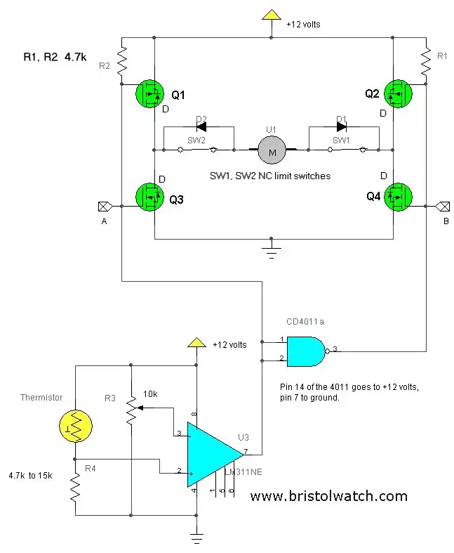
The above circuit was developed to open/close a greenhouse window when the temperature exceeded 120 degrees F. This used a 12-volt window motor from an automobile door window.
I wanted to avoid the hassle and cost of using a micro-controller and use inexpensive common parts. The power source was a 12-volt solar panel system charging a battery. This is presented to demonstrate simple, but useful circuits.
Parts list:
Q1, Q2, P-channel MOSFET IRF9630
Q3, Q4, N-channel MOSFET IRF630
D1, D2, 6 amp silicon diode.
How it works
The Lm311 voltage comparator' output is +12 volts when the voltage at the junction the thermistor and R4 is below that of the trip point adjustment R3. At this point MOSFET Q3 is turned on, MOSFET Q1 is turned off, while the 0 volt output of the Cd4011 turns on MOSFET Q2 and MOSFET Q4 off.
This provides a complete current path from MOSFET Q3, though the motor, and through MOSFET Q2. The motor will run until limit switch Sw1 opens. Diode D1 blocks any further current flow shutting the motor off. I assume the window is closed at this point.
Note the direction of rotation in a DC motor is controlled by the battery polarity. Note the direction of the diodes and motor polarity! The Cd4011 acts as an inverter and can be replaced by other CMOS ICs. The LM311 can be replaced with a Lm339 etc. Don't use 5-volt logic or exceed 15 volts. See Voltage Comparator Information And Circuits for more on voltage comparators.
As the greenhouse heats up the resistance of the thermistor drops and the voltage at the thermistor/R4 junction increases. When this voltage reaches the voltage set by R3, the Lm311 comparator will turn on and the output will go to 0 volts. This will turn on MOSFET Q1 and MOSFET Q2 off, and through the Cd4011 turns Q4 on and Q3 off.
This created a reversed polarity current path through Q1, the motor, diode D1, and Q4. The motor will run until limit switch Sw2 opens and D2 blocks any further current flow. I assume the window is now open to allow ventilation.
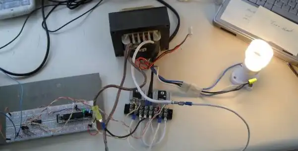
This was tested on a satellite dish positioner jack with built in limit switches. While designed for 36 volts it operated fine at 12 volts with no load.
- Quick navigation of this website:
- Basic Electronics Learning and Projects
- Basic Solid State Component Projects
- Arduino Microcontroller Projects
- Raspberry Pi Electronics, Programming
A Hall sensor in its most basic form is an analog integrated circuit. It consists of a Hall plate that outputs a "transverse" voltage based on the intensity of a magnetic field - polarity is dependant on magnetic polarity.
It also consists of a high gain differential amplifier because the generated voltage is small. The output voltage is analog usually centered around half the power supply voltage.
The addition of a Schmitt trigger with a properly set hysteresis will create a Hall switch or Hall latch. They often have an open collector output transistor.
The Schmitt triggers used here are based on an analog comparator. These can be built from operational amplifiers (op-amps) like the LM358 or LM741.
Or one can use the LM311 or LM339 quad comparator. The have open collector outputs unlike the LM311/LM741.
Often considered "digital" at this point we have in reality a one-bit analog-to-digital converter.
- Comparator Theory Circuits Tutorial
- Comparator Hysteresis and Schmitt Triggers
- Voltage Comparator Information And Circuits
- Looking at Window Comparator Circuits
- Build Autotransformer-Variac AC and DC Power Supply
- Connecting Transformers in Series-Parallel
- Build an Adjustable 0-34 volt power supply with the LM317
- AC Power Supply Rectification
- Basic Power Transformers
- Transistor-Zener Diode Regulator Circuits
- Tips for the LM78XX Series Voltage Regulators
- Bi-Polar Power Supplies
- Connecting Series-Parallel Batteries
- ULN2003A Darlington Transistor Array with Circuit Examples
- Tutorial Using TIP120 and TIP125 Power Darlington Transistors
- Driving 2N3055-MJ2955 Darlington Transistors
- Understanding Bipolar Transistor Switches
- N-Channel Power MOSFET Switching Tutorial
- P-Channel Power MOSFET Switch Tutorial
- H-Bridge Motor Control with Power MOSFETs
- Arduino Controlled IR2110 Based H-Bridge HV Motor Control
- IGBT Based High Voltage H-Bridge DC Motor Control
- More Power MOSFET H-Bridge Circuit Examples
- Build a High Power Transistor H-Bridge Motor Control
- Basic Triacs and SCRs
- Constant Current Circuits with the LM334
- LM334 CCS Circuits with Thermistors, Photocells
- LM317 Constant Current Source Circuits
- TA8050P H-Bridge Motor Control
- All NPN Transistor H-Bridge Motor Control
- Basic Triacs and SCRs
- Comparator Theory Circuits Tutorial
Web site Copyright Lewis Loflin, All rights reserved.
If using this material on another site, please provide a link back to my site.