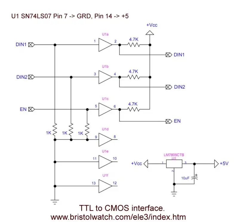
Fig. 1 7417 TTL to CMOS interface circuit.
Review Connecting Digital Logic and Transistors
by Lewis Loflin
The final goal is the interface circuit shown in Fig. 1. 3.3 or 5 volt logic can be connected to 3-15-volt CMOS logic.
The ultimate goal is the H-Bridge shown as hb_big2.jpg
See the YouTube video Simple Digital Interface Circuits.
An alternate way to interface logic and transistors is with optocouplers. See the following:
There are two basic types of bipolar transistors - NPN and PNP. They do the same other than current flow is in opposite directions. Another variation is known as Darlington transistors. This configuration uses two transistors connected together to produce very high current gain. You will need to know these parts.
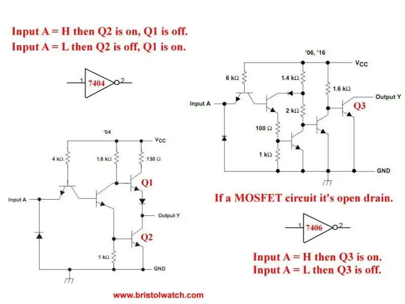
Fig. 2 TTL inverter circuits SN74LS04 and SN74LS06
TTL or transistor-transistor logic uses bipolar transistors. They operate at mostly 5-volts and are current operated devices. They use far more current than CMOS parts. Early versions of TTL have been around at least 50 years.
Fig.2 illustrates the internal diagrams for the SN74LS04 and the SN74LS06. Note the open collector output on the SN74LS06. This allows with pull up resister an interface to higher voltage logic such as the CD4000 series CMOS integrated circuits.
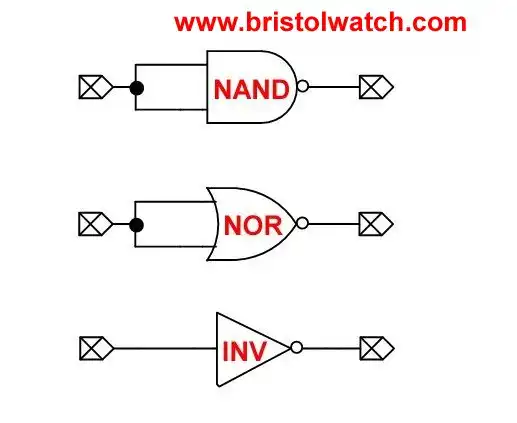
Fig. 3 Connecting NAND and NOR gates to form inverters.
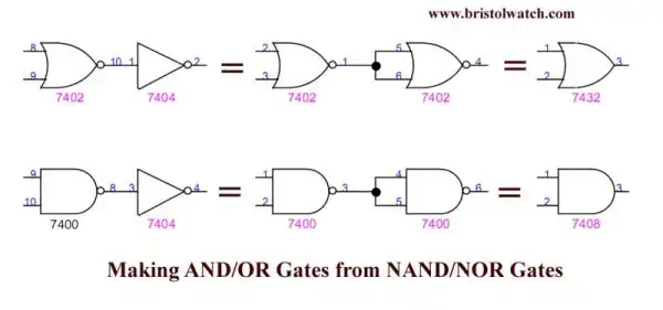
Fig. 4 Connecting NAND and NOR gates with inverter to create AND OR gates.
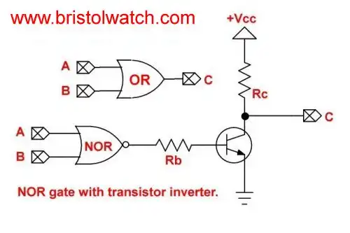
Fig. 5 NPN transistor on NOR gate out creates open-collector OR gate driving a higher voltage load.
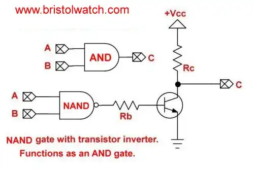
Fig. 6 NPN transistor on NAND gate out creates open-collector AND gate driving a higher voltage load.
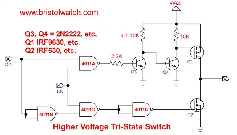
Fig. 7 Tri-State switch with NPN transistors for higher voltage output.
For more in Fig. 7 see Non-Inverting Tri-State Buffer-Switch Demo Circuit
Understanding basic digital circuits is key to understanding how to connect a computer or controller to operate a robot or read sensors in a greenhouse. Understand switching circuits, solid state relays, etc. means turning on a ventilation fan or a AC water pump.
Understanding basic chemistry allows one to monitor Ph or understand how a semiconductor device works. And knowledge of math and science makes understanding AC-DC motor operation possible and where to use them.
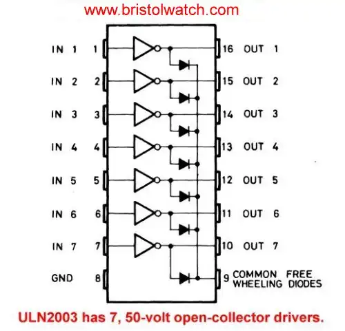
Fig. 8
Fig. 8 is the ULN2003 transistor array. It contains 7 complete NPN Darlington transistor drivers with open-collector output and suppressor diode for magnetic loads.
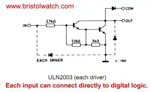
Fig. 9
Fig. 9 is the diagram of each internal driver. The input resistor allows direct connection to digital logic. For more on the ULN2003:
See ULN2003A Darlington Transistor Array with Circuit Examples.
As a former adjunct instructor it became obvious when a student had even a basic chemistry or physics class in high school how fast they could grasp electricity or electronics. Many grow frustrated and quit because they lacked even basic science or math out of high school.
You must learn the basics. That is the goal of this series of lessons.
- Exploring Solid State Relays and Control Circuits
- Comparing Photo Triac, Photo SCR Opto-Couplers
- Light Activated SCR Based Optocouplers Circuit Examples
- Silicon Controlled Rectifier Review and Circuits
- Silicon Controlled Rectifiers Connected as Power Triacs
- Insulated Gate Bipolar Transistor IGBT Circuits
- Current Limiter Circuits for Opto-Coupler LEDs
- VOM1271 Photovoltaic MOSFET Driver Circuits
- Current Limiter Allows Safe Testing of Zener Diodes, LEDs
- 3 Amp LM741 Op-Amp Constant Current Source
- Bidirectional Solid State Relay Circuits
- Simple Solid State Relay for Low Power LED 120V Lamps
- Build High Power MOSFET Directional Switch Relay
- Optical Isolation of H-Bridge Motor Controls
- All NPN Transistor H-Bridge Motor Control
- Basic Transistor Driver Circuits for Micro-Controllers
- ULN2003A Darlington Transistor Array with Circuit Examples
- Tutorial Using TIP120 and TIP125 Power Darlington Transistors
- Driving 2N3055-MJ2955 Power Transistors with Darlington Transistors
- Understanding Bipolar Transistor Switches
- N-Channel Power MOSFET Switching Tutorial
- P-Channel Power MOSFET Switch Tutorial
- Build a Transistor H-Bridge Motor Control
- H-Bridge Motor Control with Power MOSFETS
- More Power MOSFET H-Bridge Circuit Examples
- Build a High Power Transistor H-Bridge Motor Control
- H-Bridge Motor Control with Power MOSFETS Updated
- Opto-Isolated Transistor Drivers for Micro-Controllers
- Comparator Theory Circuits Tutorial
- Constant Current Circuits with the LM334
- LM334 CCS Circuits with Thermistors, Photocells
- LM317 Constant Current Source Circuits
- TA8050P H-Bridge Motor Control
- All NPN Transistor H-Bridge Motor Control
- Basic Triacs and SCRs
- Comparator Hysteresis and Schmitt Triggers
- Comparator Theory Circuits Tutorial
- Photodiode Circuits Operation and Uses
- Optocoupler MOSFET DC Relays Using Photovoltaic drivers
- Connecting Crydom MOSFET Solid State Relays
- Photodiode Op-Amp Circuits Tutorial
- Optocoupler Input Circuits for PLC
- H11L1, 6N137A, FED8183, TLP2662 Digital Output Optocouplers
- Optical Isolation of H-Bridge Motor Controls
- All NPN Transistor H-Bridge Motor Control
© Copyright 2019 Lewis Loflin E-Mail